Research Article
Novel Design of 3D Imaging Pixel On-chip Using a Micro-conjugate Mirror System
Suphanchai Punthawanunt 1, Preecha P. Yupapin 1, 2*, Prateep Phataracorn 2
1 Interdisciplinary Research Center, Faculty of Science and Technology, Kasem Bundit University, Bangkok 10250, Thailand
2 Spintronics Research Center, Department of Physics, Faculty of Science, Kasetsart University, Bangkok 10900, Thailand
* Corresponding author. E-mail: preecha.yup@kbu.ac.th
Received: May 11, 2015; Accepted: Jun. 10, 2015; Published: Jun. 20, 2015.
Citation: Suphanchai Punthawanunt, Preecha P. Yupapin and Prateep Phataracorn. Novel Design of 3D Imaging Pixel On-chip Using a Micro- conjugate Mirror System. Nano Biomed. Eng. 2015, 7(2), 52-61.
DOI: 10.5101/nbe.v7i2.p52-61.
Abstract
We have proposed the novel design of 3D imaging pixel on-chip using a micro-conjugate mirror system, where the nonlinear microring resonator known as a Panda ring resonator is designed to form the micro-conjugate mirror, which can be used to construct a three dimensional (3D) imaging system. Two micro-conjugate mirrors are vertically formed by stacking the two nonlinear Panda rings, which can be used to manipulate the 3D imaging perception, from which the human 3D vision can be replaced by a large area single eye device. In application, a thin film device of a single eye on- chip can be modeled and the artificial eye constructed. Simulation results obtained have shown that the single point (pixel) of an object can be interpreted to form the 3D image by the device whispering gallery modes (WGMs), from which the reference and the object beams are interfered and the 3D pixel formed. Finally, the holographic display information can be interpreted by the optic nerves and brain processing cells. The 3D image output signals can be confirmed theoretically by the symmetrical imaging signals.
Keywords: Aritficial eye; 3D imaging device; Single eye; Eye on-chip; Eye tracker; Single eye configuration
Introduction
Recently, a group of scientists have shown the very promising works that a device known as a Panda ring resonator, which is a nonlinear microring resonator and shown the merits of various applications for such as in nanomedicine [1], micro-electronics [2], micro energy dvice [3, 4], nano-communication [5] and nano-cosmetics [6]. Such a device was designed and shown the potential of construction (fabrication), from which the thin film device can be made eventually. By using the Panda ring resonator, the whispering gallery modes outputs can be controlled and generated by the two nonlinear side rings easier than the integrated microring resonators. This device has also shown the interesting behaviors when the different wave forms are input into the system, thus, when the Gaussian, soliton and photon are input into the device [7-9], the output results obtained have shown the different aspects that are suitable for different usages [10-17]. One of the interesting aspects is that when the output is obtained in the form of whispering gallery modes (WGMs) [18], where principally they are the tunneling photons and formed at the center Panda ring device. Moreover, there are some modes of photons that they are the leaky modes occurred spreading over the device. However, in practice they can be controlled by controlling the device parameters, where finally, the required output modes can be obtained.Artificial eye researches and investigations have been the interesting works [19], where the merits of them are useful for disability eye users, where the replacement of normal eye is the challenge. The eye user can keep their eyes in the rest condition, in which the artificial eyes can connect to the optic nerves and brain signal processing while the active eyes are in the at rest conditions, the last longer life usage can be applied and realized. This is a single point (pixel) device model, which can be used for large area applications, in which the use for 3D image display, 3D image sensors and 3D digital recording system are included. Naturally, the 3D image can be viewed by only single eye, but it will need time to adjust the body state for at least 3-5 years [20], which is the human being condition. Therefore, the single eye device and system have become the challenge of researches and investigations. In this work, is the new form of 3D image perception, uses the two vertical micro- conjugate mirrors to form the single artificial eye, from which the 3D image signals can be connected to the brain cells, where the 3D image signal processing can be functioned. In this model, the artificial can be replaced by the thin film device, where the object and reference beams are generated by the two panda rings, from which the image construction can be generated and changed to be the electrical signal in the nervous system, where scientifically, the human 3D image perception is constructed by both two eyes, where the holographic image is formed and connected to brain processing cells via the retina nerves (optic nerves).In this work, the model of double micro-conjugate mirror system is analyzed and the simulation results presented and discussed. The 3D imaging perception is manipulated using the single eye perception concept. The nonlinear micro-ring resonator material is InGaAsP/InP [21]. In simulation, the object and reference beam outputs are formed by the device WGMs, from which the single point (pixel) of the sample(object) can be presented in the form of 3D imaging signals, which can be connected to the optic nerves in the brain processing cells and the 3D image can be presented (display). The four wave mixing (FWM) signals are interpreted to confirm the 3D imaging outputs, where more details are given in the following sections.
The Model
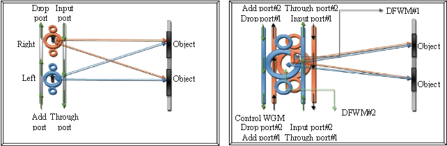
The holographic image using a single eye model is as shown in Figs. 1 and 2. The system is consisted of double micro-conjugate mirrors, where the interference beams are formed when the monochromatic light source from a laser with the certain wavelength is input into the system via the input port of the top micro- conjugate mirror, where the WGMs are generated within the top and bottom conjugate mirrors. The theoretical description of a single conjugate mirror was well described and found in reference [18]. In this work, the interference beams are formed by both top and bottom conjugate mirrors in the forms of WGM and FWM outputs, while in principally the nonlinear effect is induced by the nonlinear side rings and transferred into the center ring. In Fig. 1(a), both eyes are replaced by the two Panda rings for a right and left eyes, respectively, from which the interference signals are constructed by the object and reference beams that were generated by the Panda rings in the forms of WGMs. Alternatively, the single eye model for 3D image construction is as shown in Fig. 1.The mathematical description of light travelling within the double Panda ring resonators (DPR) is manipulated under the requirements that the WGMs and degenerated four-wave mixing (DFWM) outputs are the required outputs [22, 23], which can be used to form and confirm the 3D image occurrence of the device, the system is as shown in Fig. 1(b). Given Ei is the electric field input into the system, from which the related electric fields are obtained and propagated within the system, where they are given by
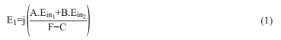
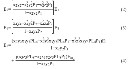
There are several parameters in Equations (1)-(4) given by the following forms.
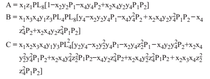
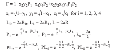
The electric (optical) fields in the Panda ring are subtituted by the new forms using the signal flow graph method [24]. When E1, E2, E3, E4 are the electric fields γ1, γ2, γ3, γ4 are the fractional coupler intensity losses (waveguide losses) κ1, κ2, κ3, κ4 are the coupling coefficients, α is an attenuation coefficient, kn=2π/λ is the wave propagation number in vacuum, L=2πR is the center ring propagation distance, L2=2πR2 is the small ring (side ring) propagation distance, j = −1 is the imaginary part of complex number, and the refractive index of the substances used in the system is defined in terms of nonlinear refractive index by [18].

where n0, n2 are the linear and nonlinear refractive indices, where for InGaAsP/InP, n0=3.14, n2=1.3×10⁻¹³ m2W-1. I and P are the optical intensity and power, respectively, Aeff is the effective mode core area [25], which is ranged between 0.10 and 0.50 um2. From Equations (2)-(5), the rearagreement of equations in the form of WGMs is taken place.
(a)(b)
Fig. 1 3D image costruction configuration using Panda ring conjugate mirror, where (a) two eyes model, (b) single eye model.
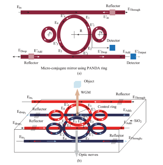
Fig. 2 Thin film model of micro-conjugate mirrors using Panda ring resonator, where (a) a signle ring, (b) double vertical conjugate mirror, where Ein: input port electric field, Ethrough: Through port electric filed, Edrop: drop port electric field, Eadd: add port electric field. Ein1 and Ein2 are the same optical field inputs into different input ports.
Results
To confirm the device performance for 3D image construction, then the device practical parameters are chosen and the manipulation formed as following details. In simulation, the manipulation of a single eye model is designed as shown in Fig. 1(b) and 3(b). Light from external (or embedded) laser source is input into the system. The laser power is 0.5 W with the center wavelength at 1.55 µm. The other parameters are given on the figure captions, where those simulation parameters were chosen close to the practical device parameters [24], the device material is AlGaAsP/InP material, which is a nonlinear material. The center ring radii are 2.0 µm, the side ring radii are 1.05 µm. The WGMs were generated and results obtained under the curtain conditions, for instance, WGM and FWM outputs. The output signals can also be monitored via the through and drop ports, in which the additional signals can be applied into the device add port, where finally the required WGMs can be obtained. In practice, the device can be fabricated and thin film device formed, from which such a device can be stacked on human fore head, where the WGM outputs can be connected to the optic nerves and the brain signal processing functioned, in which the 3D image is established and the artificial vision using a single eye realized. Simulation results of the artificial eye model using the FDTD (Finite Difference Time Domain) simulation program [25, 26] can be employed as following details, from which the device parameters are chosen closely to the practical device parameters. The input laser source peak power used is 0.5 W, with the center wavelength is at 1.55 µm. The waveguide loss (γ) is 0.01, the attenuation loss (α) is 0.1dBmm-1. The coupling constant (κ) is 0.5. The ring circumference is 2πr, where r is a ring radius. The wave number (k n ) in vacuum is 2π/λ n ). In most of the cases, the centering radii are 2.0 µm, the side ring radii are 1.0 µm. To form the 3D image of a single pixel using the WGMs, therefore, the device parameters can be chosen to control the obtained WGM outputs, in which the reference and object beams are formed by the WGM light beams in both cases (a) two eyes and (b) single eye models, which will be manipulated using MATLAB program and FDTD (Opti-wave) software. In Fig. 2, a single point on the sample (object) is viewed by the WGM beams of two conjugate mirrors, where the image information (signal) is then connected to the optic nerves. The device output signals can be seen at the center (WGMs) and device output ports by the live vision and light detector, respectively. In Fig. 3, the simulation results of the 3D image model using FDTD software, where (a) a device model, (b) WGMs output, (c) FWM output, (d) WGM output at the center ring, (e) and (f) are the side ring WGMs outputs. In Fig. 4, the simulation results in terms of wavelengths with the center ring radii are 2.0 µm, right ring and left ring radii are 1.05 µm, the reflection distance = 1.0 µm and 1.5 µm, where (a) the result of electric field intensity of the center ring (b) Thought port and (c) Drop port FMW outputs, PCM: Phase Conjugate Mirror. In Fig. 5, the results of WGMs in the double Panda ring (DPR) system with bottom Panda ring control, the bottom panda electric field = 0.75 a.u., the upper Panda ring electric field = 1 a.u., where (a) the center ring FWM output, (b) the center ring WGM output at the Through port, (c) WGM drop port output with the center ring radii are 2.0 µm, right and left ring radii are 1.05 µm, the reflection distance = 1.0 µm and 1.5 µm, respectively, the coupling constants are κ1 = κ2 = κ3 = κ4 = 0.5. In Fig. 6, the results of WGMs in the double Panda ring system with bottom Panda ring control, the bottom panda electric field = 1.75 a.u., the upper Panda ring electric field = 1 a.u., where (a) center ring FWM output, (b) the center ring WGM output at the Through port, (c) WGM drop port output with the center ring radii are 2.0 µm, right and left ring radii are 1.05 µm, the reflection distance = 1.0 µm and 1.5 µm, respectively, the coupling constants are κ1 = κ2 = κ3 = κ4 = 0.5. In Fig. 7, the results of 3D image under the FWM condition control using the InGaAsP/InP material, Aeff is the effective mode core area, where Aeff = 0.35 µm 2 , neff = 3.34, n2 =1.3×10⁻¹³ cm2 /W, and γ1 =γ2 =γ3 =γ4 =0.01. In this figure the 3D image present only one point (pixel) of the sample (object), where in application, the source (object) scanning range can be applied to obtain the large volume of 3D image, on the other hands, the device array can be used replacing the scanning range. The summary of the waveguide structure and variable parameters of the proposed system is given in the Table 1.
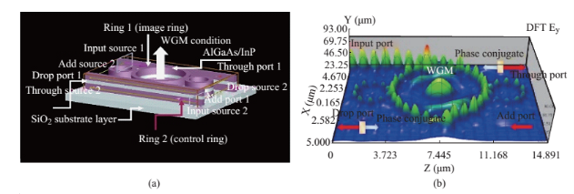
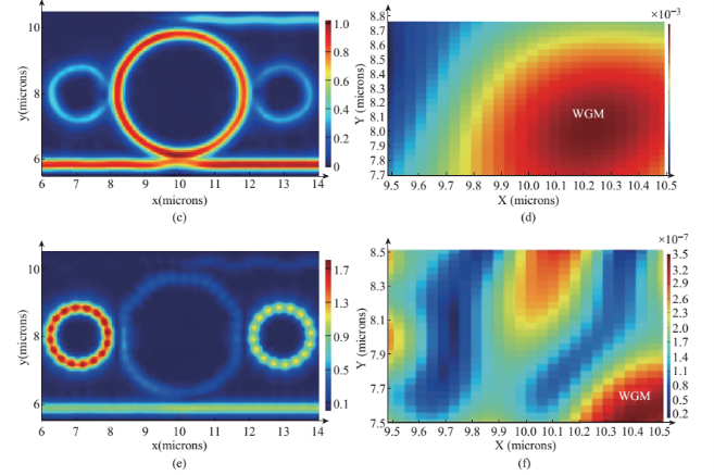
Fig. 3 Simulation results of the 3D image model using FDTD software, where (a) a device model, (b) WGMs output, (c) FWM output, (d)WGM output at the center ring,(e) and (f)are the side ring WGMs outputs.
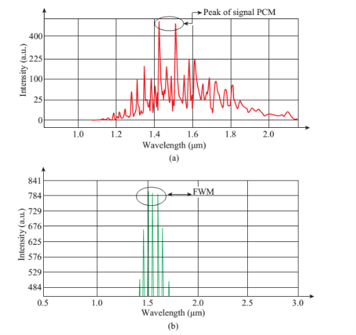
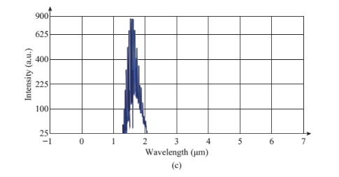
Fig. 4 Simulation results of the ring (top ring) in terms of wavelengths with the center ring radii are 2.0 μm, right and left ring radii are 1.05 μm, where the reflection distance = 1.0 μm and 1.5 μm, using using equations (2)-(5), (a) the result of electric field intensity of the center ring, (b) Thought port and (c) Drop port FMW outputs, PCM: Phase Conjugate Mirror.
Table 1: Waveguide structure and variable parameters of the proposed system
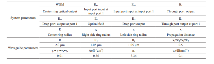
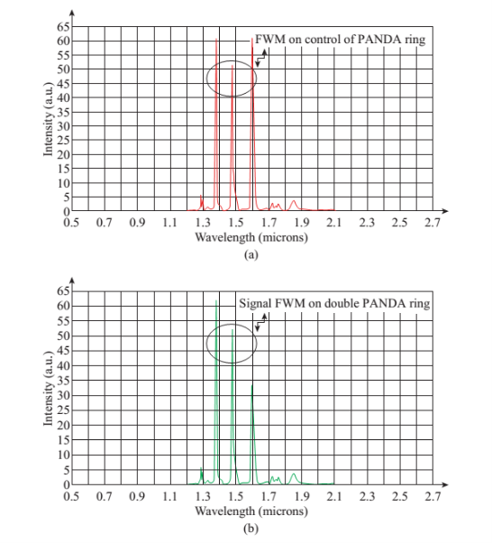
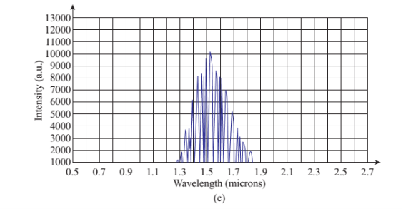
Fig. 5 Results of WGMs in the double Panda ring (DPR) system with bottom Panda ring control, the bottom panda eleectric field= 0.75 a.u., the upper Panda ring electric field = 1 a.u., where (a) the center ring FWM output, (b) the WGM of center ring at the Through port, (c) WGM drop port output with the center ring radii are 2.0 μm, right and left ring radii are 1.05 μm, the reflection distance = 1.0 μm and 1.5 μm, respectively, the couplong constants are λ1=λ2=λ3=λ4=0.5.
Discussions
The 3D image construction and perception system as shown in Fig. 2(b) and 3(a), are described as following details. The desired WGM of the top phase conjugate mirror (PCM) is formed and projected on the object (pixel) as shown in Fig. 4, where the FWM is generated by the reflected beam in the opposite direction of incident beam formed as shown in Fig. 3. The interference between the reference and object beams is established within the top PCM and transrfered into the bottom PCM, from which the 3D image pixel is generated within the bottom PCM as shown in Figs. 5 and 6, where the generated WGM by the bottom PCM is connected to the optic nerves and brain cells, where finally the 3D imaging pixel is interpreted by the brain processing cells. The contrast 3D image is obtained by the FDTD program as shown in Fig. 7, which is supported by the symmetrical FWM outputs in Figs. 5 and 6.
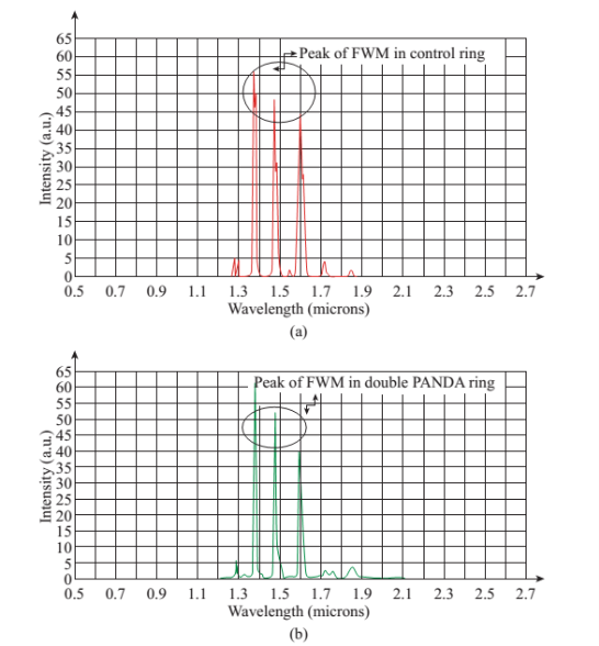
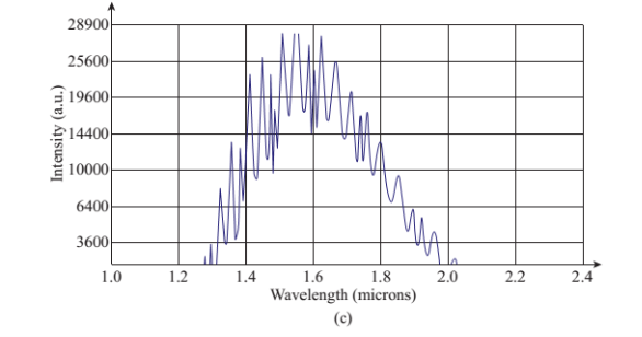
Fig. 6 Results of WGMs in the double Panda ring (DPR) system with bottom Panda ring control, where the bottom panda eleectric field = 1.75 a.u., the upper Panda ring electric field = 1 a.u., where (a) center ring FWM output, (b) WGM output of the center ring at the Through port, (c) WGM drop port output with the center ring radii are 2.0 μm , right and left ring radii are 1.05 μm , the reflection distance = 1.0 μm and 1.5 μm , respectively, the couplong constants are λ1=λ2=λ3=λ4=0.5.
Conclusions
We have shown that the 3D imaging construction and perception (display) of a single point (pixel) can be modeled and manipulated using a double Panda conjugate mirror system, where in practice such a device can be potentially fabricated and used, which is implied that the large area device can be formed by the device array (or scanning range device) for large area applications. The real (live) 3D images can be constructed and display by the WGMs at the center ring outputs, where principally in this concept the object and reference beams can be constructed and well confirmed by the symmetrical FWM output signals. Moreover, the device can also be designed and used for more related applications such as imaging sensors, brain signal sensors and 3D imaging display panel, which will be our continuing research works.
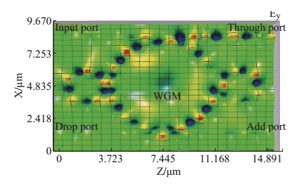
Fig. 7 Results of 3D image under the FWM conditon control using the InGaAsP/InP material, Aeff is the effective mode core narea Aeff=0.3 μm2, neff=3.14, n2=1.3×10⁻¹³ cm2/W, λ1=λ2=λ3=λ4=0.01.
Acknowledgments
The author would like to give the acknowledgement to King Mongkut’s Institute of Technology Ladkrabang (KMITL), Bangkok 10520, Thailand for the research laboratory facilities.
Disclosure
There is no conflict of interests regarding the publication of this article.
References
[1] M.A. Jalil, N. Suwanpayak, K. Kulsirirat et al., Embedded Nanomicro Syringe on Chip for Molecular Therapy, International Journal of Nanomedicine, 2011, 6: 2925-2932
[2] S. Chantanetra, C. Teeka, S. Mitatha et al., Hybrid Transistor Manipulation Contrlloed by Light within a
Panda Microring Resonator, 2012, 11(2): 125-130.
[3] S. Duad, S. Ueammanapong, S. Srithanachai etal., Particle Accellerator using Optical tweezer for Photodetector Performance Improvement, IEEE Transaction on Nanotechnology, 2012, 11(6): 1087-1092.
[4] F.D. Zainol, R. Jomtarak, S. Duad et al., Atom Bottom-up Manipulation Controlled by Light for Microbattery Use, IEEE Transaction on Nanotechnology, 2012, 11(5): 934-939.
[5] I.S. Amiri, S.E. Alavi, S.M. Idrus et al., IEEE 802.15.3c WPAN Standard Using Millimeter Optical Soliton Pulse generated by a Panda Ring Resonator, IEEE Photonics Journal, 2013, 5(5), Article # 7901912.
[6] P.P. Yupapin, S. Suwandee, Drug Targeting Model of Composite Gold Tourmaline for Cells Enhancing
Applications, Nano Biomedicine and Engineering, 2015, 7(2): 38-46.
[7] I.S. Amiri, S.E. Alavi, S.M. Idrus, W-band OFDM Transmission for Radio-Over-Fiber Link Using Solitonic
Millimeter wave generated by MRR, IEEE Quantum Electronics, 2014, 50(8): 622-626.
[8] C. Sirawattananon, M. Bahadorun, J. Ali et al, Analytical Vernier Effects of a Panda Ring Resonator for
Microforce Sensing Applications, IEEE Transaction on Nanotechnology, 2012, 11(4):707-712.
[9] A. Mohamad, M. Bahadorun, A.F.A. Noorden et al., Modified Add-drop Microring Resonator for Temperature Sensing, Journal of Computational and Theoretical Nanoscience, 2015, 12: 1-6.
[10] I.S. Amiri, J. Ali, Deform of Biological Human Tissue using Inserted Force Applied by Optical Tweezers Generated by PANDA Ring Resonator, Quantum Matter., 2014, 3: 24-28.
[11] S.E. Alavi, I.S. Amiri, A.S.M. Supa’at et al., Generation of Femtosecond Soliton Tweezers using a Half-Panda System for Modeling the Trapping of a Human Red Blood Cell, Journal of Computational and Theoretical Nanoscience (JCTN), 2015, 12: 10-18.
[12] I.S. Amiri, A. Afroozeh, H. Ahmad, Integrated micro- ring photonics: Principles and Applications as Slow light devices, Soliton generation and Optical transmission, CRC Press, 2015.
[13] I.S. Amiri, J. Ali, Nano Particle Trapping by Ultra- short Tweezer and Wells using MRR Interferometer System for Spectroscopy Application, Nanoscience and Nanotechnology Letters, 2013, 5(8): 850-856.
[14] I.S. Amiri, J. Ali, Nano Optical Tweezers Generation used for Heat Surgery of a Human Tissue Cancer Cells using Add/Drop Interferometer System, Quantum Matter, 2013, 2: 489-493.
[15] I.S. Amiri, J. Ali, Optical Buffer Application used for Tissue Surgery using Direct Interaction of Nano Optical Tweezers with Nano Cells, Quantum Matter, 2013, 2: 484-488.
[16] I.S. Amiri, B. Barati, P. Sanati et al., Optical Stretcher of Biological Cells using Sub-nanometer Optical Tweezers Generated by an Add/Drop Microring Resonator System, Nanoscience and Nanotechnology Letters, 2014, 6: 111-117.
[17] I.S. Amiri, A. Nikoukar, Ali, J. et al., Ultra-short of Pico and Femtosecond Soliton Laser Pulse using Microring Resonator for Cancer Cells Treatment, Quantum Matter, 2012, 1: 159-165.
[18] N. Sarapat, T.D. Frank, P.P. Yupapin, Conjugate Mirror Design and Simulation using a Nonlinear Coupling Microring Circuit, Journal of Nonlinear Optical Physics and Materials, 2013, 22 (3): 1350024.
[19] N. Thammawongsa, P.P. Yupapin, Remote Artificial Eyes using Micro-optical Circuit for Long Distance Imaging Perception, Artificial Cells, Nanomedicine and Biotechnology, 2014, 1-5: Posted online on 20 May 2014.
[20] N. Thammawongsa, J. Ali, P.P. Yupapin, Artificial Vision Model by Small Scale Conjugate Mirror, Journal of Biosensors and Bioelectronics, 2013, 4: 125e.
[21] Y. Kokubun, Y. Hatakeyama, M. Ogata et al., Fabrication Technologies for Vertically Coupled Micro Ring Resonator with Multilevel Crossing Busline and Ultracompact-Ring Radius, IEEE J. Sel. Top. Quant. Electron, 2005, 11(1): 4-10.
[22] K. Tamee, K. Chaiwong, K. Yothapakdee et al., 3D Imaging Generated by Micro-Optical Devices System with Distortion Improvement, J. ICIC Express Letters, 2015, 8(3): 707-711.
[23] K. Yothapakdee, P.P. Yupapin, K. Tamee, Brain Signal Monitoring Model Using THz Whispering Gallery Modes Generated by Micro-conjugate Mirror Probe, IFSA Sensors and Transducers, 2015, 186(3): 112-117.
[24] M. Bahadorun, J. Ali, P.P. Yupapin, Ultrafast All-optical Switching using Signal Flow Graph for Panda Resonator, Applied Optics, 2013, 52(12): 2866-2873.
[25] N. Thammawongsa, S. Mitatha, P. P. Yupapin, Optical Spins and Nano-Antenna Array for Magnetic Therapy, J. IEEE Transaction on Nanobioscience, 2013, 12(3): 228-232.
[26] OptiFDTD by Opti-wave Corporation Company, Version 8.0, single license, 2008.
Copyright© 2015 Suphanchai Punthawanunt, Preecha P. Yupapin and Prateep Phataracorn. This is an open-access article distributed under the terms of the Creative Commons Attribution License, which permits unrestricted use, distribution, and reproduction in any medium, provided the original author and source are credited.

|
Nano Biomedicine and Engineering. Copyright © Shanghai Jiao Tong University Press |
 |