Research Article
Biomechanical Study between the Rigid and Dynamic Fixation Systems of the Spinal Column Analyzed by the Finite Element Method
Samir Zahaf *, Said Kebdani
Département de génie mécanique, université des sciences et de la technologie d’Oran Mohamed Boudiaf, USTO-MB, BP 1505, EL M’naouer, 31000 Oran Algérie. (Department of Mechanical Engineering, University of Science and Technology Mohamed Boudiaf (USTO-MB), El Mnaouar, PO Box 1505, Bir El Djir 31000, Oran, Algeria.)
* Corresponding author. E-mail: samir.zehaf@univ-usto.dz, zahafsamir1983@gmail.com or kebdani_sd@yahoo.fr Tel.:+213-56131183
Received: May 31, 2017; Accepted: Jun. 27, 2017; Published: Jun. 30, 2017
Citation: Samir Zahaf, Said Kebdani, Biomechanical Study between the Rigid and Dynamic Fixation Systems of the Spinal Column Analyzed by the Finite Element Method. Nano Biomed. Eng., 2017, 9(2): 169-183.
DOI: 10.5101/nbe.v9i2.p169-183.
Abstract
Orthopedic fixation devices are widely used in treatment of spinal diseases. It is expected that application of dynamic stabilization confers valuable movement possibility besides its main role of load bearing. Comparative investigation between pedicle screw model rigid fixation and (B Dyne, Elaspine, Bioflex, Coflex rivet) models dynamic fixation systems may elucidate the efficacy of each design. The goal of the present study is to evaluate the efficacy of five fixation systems mounted on L4-L5 motion segment. In this numerical study, a 3D precious model of L4, L5 and their intervertebral disc has been employed based on CT images. Five fixation devices have been also implanted internally to the motion segment. Finite element method was used to evaluate stress distribution in the disc and determine the overall displacement of the segment as a measure of movement possibility. The results show that the Coflex rivet implantation can provide stability in all motions and reduce disc annulus stress at the surgical segment L4-L5. On the other hand, maximum stress in the disc has been observed in dynamic systems but within the safe range. The greater movement of the motion segment has also appeared in dynamic fixations. Existence of the fixation systems reduced the stress on the intervertebral disc which might be exerted in intact cases. Use of the fixation devices can considerably reduce the load on the discs and prepare conditions for healing of the injured ones. Furthermore, dynamic modes of fixation confer possibility of movement to the motion segments in order to facilitate the spinal activities.
Keywords: Lumbar spinal stenosis; Interspinous; Coflex rivet; B Dyne; Bioflex; Elaspine; Pedicle screw fixation; Disc annulus; Von Mises stress; Finite element analysis
Abbreviation: ALL = anterior longitudinal ligament; PLL = posterior longitudinal ligament; TL = transverse ligament; LF = ligamentum flavum; ISL = interspinous ligament; SSL = supraspinous ligament; CL = capsular ligament; SL = sacrotuberous ligament; SPL = sacroiliac posterior ligament; IL = interosseous ligament; PLIF = posterior lumbar interbody fusion; DIV = disc intervertebral
Introduction
Lumbar spinal stenosis (LSS) is a common disabling disease in the elderly. The reduced disc height narrows the spinal canal and the neural foramina, eventually resulting in nerve compression [1]. The symptoms of LSS include bilateral radicular pain and intermittent neurogenic claudication, sensation disturbance and loss of muscle strength in the legs. Many surgeons perform decompression for spinal stenosis and reconstruct the segment with rigid fusion devices. However, rigid fusion may cause increased stress at the adjacent discs, resulting in degeneration of adjacent segments [2-4]. Therefore, flexible non fusion devices such as the interspinous process device were developed with the intention of reducing adjacent segment degeneration. Spinal disorders (SDs) include a variety of malfunctions in vertebral complex which have been considered as one of the most relevant diseases in the population. SDs can be related to many factors such as occupational conditions, age, weight, etc [5-8], that take considerable costs annually [7]. The origin of pain as the main symptom for SDs may be various and elaborative like muscular spasm, weakness or damage [10], damages due to overstretch or overpressure of the existing soft tissue like intervertebral discs (IVD), fascias, tendons and ligaments [11], vertebral damages [12], and spinal cord stimuli [13]. In SD cases, the motion segment should be immobilized in order to avoid such movements that deteriorate the case and prevent the healing process [14]. The first choice is, hence, fusion of the motion segment by rigid instrumentation [15-19]. Although the level of stress in the components becomes less in rigid fixation systems, several limitations in back natural motions and discomforts emerge. In a retrospective study, it was shown that the patient reported various levels of comfort and satisfaction after the surgery and implantation [21-22]. Moreover, immobility of one or more segments endangers adjacent segments due to higher share of loading they received followed by revision or re-intervention [23-29]. These problems have been mastered by using recently-developed systems of fixation, called dynamic stabilization system for the spine [30-31]. In these designs, the previous rigid rod has been replaced by more flexible alternatives. For needs of flexibility a spring-shaped connector has been used to provide slight but influencing movement between the vertebrae to perform the kinematic tasks [32]. Another dynamic fixation system contains polymer spacer between pedicles screws which covers a wire passes through the holes [32-35]. It has been expected that the use of these dynamic systems facilitates the motion of lumbar or thoracic segment underwent fixations. The dynamic fixation systems, so-called Dynesys, have been employed first by Stoll et al. but then formally introduced by Dubois et al. [31-36]. Retrospective studies by Cakir et al. showed that Dynesys worked slightly better and reduced the operation time and hospital stay, and hence, could be introduced as an effective alternative to fusion in patients [37]. Kim et al. compared the kinematic behavior of spinal fixation systems, including rigid and dynamic ones by virtual human model at the level of L4-S1. They found that the Dynesys system revealed similar kinematic behaviors to the intact model [38]. Cunningham et al. evaluated the safety and efficacy of the Dynesys systems and associated in-vitro and in-vivo effects in animal models. They used wire and polymer spacer type of Dynesys and concluded that it stabilized spinal motion. Also, 25% of screw loosening was observed after 12 months [33]. Besides the experimental studies, numerical approaches have been further used to examine the efficacy of the dynamic systems of spinal stabilization. Shin et al. developed a finite element model of the human lumbar spine to calculate the stiffness of fixation systems implanted on the levels of L2-L5. Their results showed that dynamic stabilization was more similar to the intact model than fused fixation [32]. In another study, Zhang et al. conducted a finite element analysis to calculate the biomechanical capacity of dynamic fixation systems in type of wire and polymer spacer and stabilization at the level of L4-L5 and indicated that the stiffness of a segment was increased in dynamic system; thus, it could significantly diminish the intervertebral disc's stress [34]. Although the efficacy of fixation systems have been separately studied, no comparative study exists to shed light on the pros and cons of these systems in a fixed model underwent to the same conditions. Moreover, the measures for the efficiency of the fixation systems vary between stress/strain in IVD and vertebrae, or the displacement of the motion segment. Therefore, the present investigation is aimed at compare the prevalent models of spine fixations including rigid, dynamic systems in a same model and loading conditions using finite element method. The principal aim of the present study is to compare the provision of movement facility for the motion segment against reduction in stress of intervertebral disc. Fig. 1 shows two vertebrae of the spinal column with an intervertebral disc under the effect of a compound loading (compression P + bending moment P1). The compressive load P creates an internal pressure in the nucleus, and this pressure will thereafter generate the disc degeneration or degenerative disc disease (Fig 2). With regards to the forward flexion P1, if the load P1 increases, automatically the distance between the point of load application and the axis of the spinal column increases. We see that the posterior portion of the annulus fibrosis is tensioned and the other front portion is compressed. That is to say the nucleus pulposus burst back (posterior compression). This compression produced by disc protrusion comes into contact with a nerve root called herniated disc.
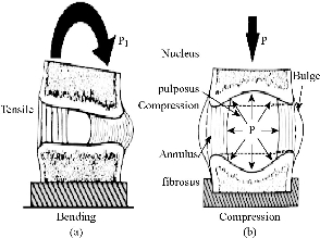
Fig. 1 The intervertebral disc with (a) bending and (b) compression [6].
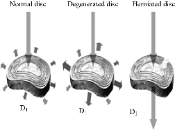
Fig. 2 Load distribution at the disc D1 according to his state [7].
Experimental
FE model of intact L4-L5 segment lumbar spine (intact model)
A validated 3D FE model of the intact L4-L5 segment was used. To create this model, computed tomography scans of the L4-L5 segment of a middle-aged healthy man were obtained at 1-mm intervals. The commercially available FE program, ANSYS 16 (ANSYS Inc., Canonsburg, PA, USA) was used to model the spinal segments. The FE model of the osseoligamentous lumbar segment included the vertebrae, one intervertebral disc, endplates, posterior elements and the following ligaments: supraspinous, interspinous, ligamentum flavum, transverse, posterior longitudinal, anterior longitudinal and capsular. The material properties of the intact L4-L5 segment were assumed to be homogeneous, and a detailed description has been presented in our previous studies [57–58]. The ligaments were simulated using ten-node link elements with tension resistance only, and the elements were arranged in the anatomic orientation. ten-node solid elements were used for modelling of the cortical bone, cancellous bone, endplate, posterior bony structure and disc. The disc annulus consisted of fibres embedded in the ground substance. Annular fibres in 6 layers were modelled using ten-node link elements with tension resistance only and placed in an anatomic orientation [59–61]. The facet joints were treated as nonlinear 3D contact pairs using surface-to-surface contact elements, and the coefficient of friction was set to 0.1 [57–58]. The material properties of the INT model are listed in (Table 1) and were chosen from previous studies [39–58]. All seven ligaments were simulated by ten node link elements with resistance tension only, and they were arranged in the anatomical direction given by the text book [54]; the cross-sectional area of each ligament was obtained from previous studies [47, 52–54]. An ten-node solid element was used for modeling the annulus ground substance. Cortical bone and cancellous bone were assumed to be homogeneous and isotropic. The intervertebral disc consisted of annulus ground substance and nucleus pulposus, which embeds collagen fibers in the ground substance. The nucleus pulposus was modeled as an incompressible fluid with bulk modulus of 1MPa by an ten-node fluid element [45–53]. The facet joint was treated as a sliding contact problem using surface-to-surface contact elements, and the coefficient of friction was set at 0.1 [55-56]. The FE model of the intact L4-L5 segment lumbar spine consisted of 199,689 elements and 32,7621nodes (Fig. 3).
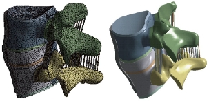
Fig. 3 FE model of L4-L5 motion segment with IVD.
FE model of bilateral B Dyne implant fixation implanted into the L4–L5 segment (B Dyne implant fixation model)
The existing geometrical model of the implant realized with CAO software (Solidworks 2016) was imported. It consisted of an assembly of five parts: the piston rod, the cylindrical body, the fixed rod, the ring and the damper block. The contact surfaces between the body and the fixed rod had a threaded area which made it possible to assemble the implant. In the manufacturing process, after assembly, these two parts were welded together. The geometry of these contact surfaces were therefore simplified on the geometric model (Fig. 4) in order to facilitate the meshing and calculation steps. The metal parts (piston rod, cylindrical body and fixed rod) were modeled in titanium TA6V ELi with elastic properties, Young’s modulus and Poisson’s ratio were assigned to be 112,400 MPa and 0.34, respectively. The deformable parts (ring and damper block) were modeled with an elastic behavior of a silicone, Young’s modulus and Poisson’s ratio were assigned to be 600 MPa and 0.49. The model B Dyne consisted of 228,348 elements and 378,676 nodes (Fig. 4).
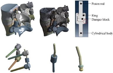
Fig. 4 FE model of the L4-L5 motion segment with posterior dynamic fixation system B Dyne.
FE model of bilateral Elaspine implant fixation implanted into the L4–L5 segment (Elaspine implant fixation model)
The Elaspine implant consistsed of six parts: four metal elements made of titanium alloy (Ti6Al4V ISO 5832-3) and two deformable rods made of polymer (silicone). A deformable rod made of polymer (silicone) with a length of 60 mm and a diameter of 7 mm, which is presented in Fig. 5. The screw-bone interfaces were assigned to be fully constrained. The material used for the pedicle screws was Ti-6Al-4V. Young’s modulus and Poisson’s ratio were assigned to be 113,000 MPa and 0.3, respectively. The two deformable parts were modeled with an elastic behavior which contained a Young’s modulus and Poisson’s ratio assigned to be 600 MPa and 0.49. The model Elaspine consisted of 223,950 elements and 373,025 nodes (Fig. 5). An assembly of two rods and four screws (spinal assembly) was required to stabilize a spinal segment. Each implant was attached to the lumbar vertebrae using titanium pedicle screws (Fig. 5).
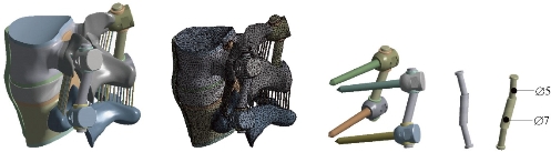
Fig. 5 FE model of the L4-L5 motion segment with posterior dynamic fixation system Elaspine.
FE model of bilateral Bioflex implant fixation implanted into the L4–L5 segment (Bioflex implant fixation model)
The Bioflex implant was a helical spring manufactured by the company BioSpine, The total length of the rod was 70 mm and the spring height 15.7 mm, The spring diameter was 5 mm and the pitch equaled 5.5 mm. The material used for the Bioflex model was Ti-6Al-4V. Young’s modulus and Poisson’s ratio were assigned to be 113,000 MPa and 0.3, respectively. The Bioflex model consisted of 228,101 elements and 399,240 nodes (Fig. 6).
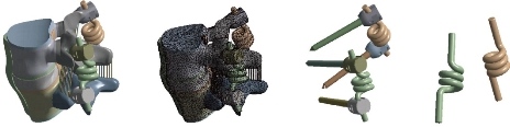
Fig. 6 FE model of the L4-L5 motion segment with posterior dynamic fixation system Bioflex.
FE model of Coflex rivet implanted into the L4–L5 segment (Coflex rivet model)
The Coflex rivet model was implanted at the L4–L5 segment. This model was used to simulate instability by cutting the ligamentum flavum. The facet capsules and 50% of the inferior bony faceted bilaterally at the L4–L5 segment (Tsai et al. 2006; Kettler et al. 2008). In addition, the supraspinous ligaments and interspinous ligaments had to be resected before insertion. The Coflex rivet differed from the original Coflex implant by adding two rivets joining the wings and spinous processes (Fig. 7). The coefficient of friction for the rest of the contact regions was set to 0.1 (Fig. 6). The rivets were simplified as cylinders and were constrained to both the holes on the wings of the Coflex and the spinous processes in all degrees of freedom (the degrees of freedom of screw nodes are interpolated, with the corresponding degrees of freedom of the nodes on the Coflex and spinous processes during the execution of ANSYS program). The material used for the Coflex rivet was a Ti-6Al-4V alloy. The Young’s modulus and Poisson’s ratio were assigned to be 113,000 MPa and 0.3 respectively. The model Coflex rivet consisted of 202,615 elements and 332,396 nodes (Fig. 7).
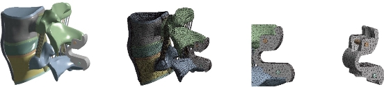
Fig. 7 FE model of the L4-L5 motion segment with posterior dynamic fixation system Coflex rivet.
FE model of bilateral pedicle screw fixation implanted into the L4–L5 segment (pedicle screw fixation model)
The pedicle screw fixation model was implanted at the L4–L5 segment. The difference between the pedicle screw fixation model and the abovementioned implantation models was that the pedicle screw fixation model preserved the supraspinous ligaments and interspinous ligaments (Fig. 8). The pedicle screw fixation consisted of two rods (diameter, 5 mm) and four pedicle screws (diameter, 5 mm). The pedicle screws were inserted through the pedicles of the L4 and L5 vertebrae bilaterally. The pedicle screws were simplified as cylinders. The screw-bone interfaces were assigned to be fully constrained. The material used for the pedicle screws was Ti-6Al-4V. Young’s modulus and Poisson’s ratio were assigned to be 113,000 MPa and 0.3, respectively. The model pedicle screw consisted of 225,769 elements and 394,288 nodes (Fig. 8). Therefore, the purpose of this work is to study the mechanical behavior between the rigid and dynamic fixation systems of the spinal column by using finite element (FE) analyses on a two-segment spinal model. In addition, comparative investigation between rigid and 4 dynamic fixation systems may elucidate the efficacy of each design. The goal of the present study is to evaluate the efficacy of four fixation systems mounted on L4-L5 motion segment. Finite element method was used to evaluate stress distribution in the disc and determine the overall displacement of the segment as a measure of movement possibility, the maximal Von Mises stress at the disc annulus and the Von Mises stress distribution at the surgical disc annulus.
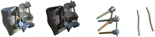
Fig. 8 FE model of the L4-L5 motion segment with posterior dynamic fixation system pedicle screw fixation.
Table 1. Material properties used in the FE model
|
Material |
Young modulus E (MPa) |
Poisson coefficient |
Ref. |
|
Cortical Bone |
12000 |
0.3 |
[39-45] |
|
Cancellous Bone |
100 |
0.2 |
[39, 41-42, 44-45] |
|
Posterior Bone |
3500 |
0.25 |
[39-41, 45-46] |
|
Cartilage Endplates |
12000 |
0.3 |
[40, 42, 47] |
|
Annulus Ground Substance |
4.2 |
0.45 |
[39-40, 42, 45, 49-50] |
|
Nucleus Pulposus |
1 |
0.499 |
[45, 48, 51-53] |
|
Anterior Longitudinal Ligament |
7.8 (<12%), 20.0 (>12%) |
0.3 |
[55, 56–58] |
|
Posterior Longitudinal Ligament |
10.0 (<11%), 20.0 (>11%) |
0.3 |
[55, 56–58] |
|
Ligamentum Flavum |
15.0 (<6.2%), 19.5 (>6.2%) |
0.3 |
[55, 56–58] |
|
Intertransverse Ligament |
10.0 (<18%), 58.7 (>18%) |
0.3 |
[55, 56–58] |
|
Inter-Spinous Ligament |
10.0 (<14%), 11.6 (>14%) |
0.3 |
[55, 56–58] |
|
Supra-Spinous Ligament |
8.0 (<20%), 15.0 (>20%) |
0.3 |
[55, 56–58] |
|
Capsular Ligament |
7.5 (<25%), 32.9 (>25%) |
0.3 |
[55, 56–58] |
Boundary and loading conditions
The loading condition was similar to the in-vitro study of Yamamoto et al., in which the intact L4-L5 segment was subjected to the maximum possible load without causing spinal injury [33]. Therefore, all four physiological motions were imposed, each with a moment P1 equal to 10.6 Nm and a compression P equal to 400 N on the superior surface of the L4 level. These models constrained all degrees of freedom at the inferior surfaces of the L5 vertebra (Fig.9).
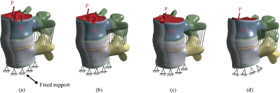
Fig. 9 Biomechanical model of the intact L4-L5 segment: (a) Anterior load (flexion); (b) Posterior load (extension); (c) Lateral load (flexion lateral); and (d) Axial load (torsion).
Results and Discussion
Two principal functions of the fixation systems were to balance the stabilization and dynamization of the motion segment, and also to reduce the over pressure on vulnerable tissues like muscles or IVDs. Therefore, overall displacement of the motion segment and stress of the IVD could be considered as measures for efficacy of the fixation systems. In flexion, the displacement total of the segment spinal (L4/L5) decreased by 36.81% in the Coflex rivet model, 29.64% in the Bioflex model, 22.29% in the Elaspine model, 21.18% in the B Dyne model and 2.47% in the pedicle screw fixation that the surgical segment (Fig. 10). On the other hand, the maximum von Mises stress of the segment spinal (L4/L5) decreased by 58.80% in the Coflex rivet model, 41.48% in the Elaspine model, 39.22% in the B Dyne model, 16.58% in the Bioflex model and 3.70 % in the pedicle screw fixation that the surgical segment. However, the displacement total of the segment spinal (L4/L5) and maximum von Mises stress of the intact disc increased by 36.81%, 58.80% in the Coflex rivet model and 2.47%, 3.70% in the pedicle screw fixation model at L4–L5 segment. In extension, the total displacement of the segment spinal (L4/L5) decreased by 20.15% in the Coflexe rivet model, 12.80% in the Elaspine model, 8.11% in the B Dyne model, 5% in the pedicle screw and 2.72% in the Bioflex model at the surgical segment (Fig. 10). After implantation, the von Mises stress effectively decreased by 40% in the Coflex rivet mode, 20.61% in the Elaspine model, 20.60% in the B Dyne model, 5.91% in the pedicle screw fixation model and 1.54% in the Bioflex model when compared with the intact model. In addition, the stress Mises were equal in the two dynamic models (B Dyne, Elaspine) but the total displacement of the segment spinal (L5/L4) increased by 12.80% in the Elaspine model and decreased by 8.11% in the B Dyne model at L4–L5 segment (Fig. 10). In lateral bending, the total displacement of the segment spinal decreased by 45.89% in the Coflex rivet model, 17.88% in the Bioflex model, 15.02% in the Elaspine model, 13.18% in the B Dyne model and 1.97% in the pedicle screw fixation model at the surgical segment, when compared with that of the intact model (Fig. 10). However, the von Mises stress in the disc intact decreased by 66.67% in the Coflex rivet, 29.71% in the Elaspine model, 29.20% in the Bioflex model, 27.86% in the B Dyne model and 2.99% in the pedicle screw fixation model at L4–L5 segment (Fig. 10). In axial rotation, the displacement anterior of the segment spinal (L5/L4) decreased by 21.53% in the Coflex rivet model, 18.24% in the Bioflex model, 15.31% in the Elaspine model, 10.57% in the B Dyne model and 2.83% pedicle screw fixation model at the surgical segment, when compared with that of the intact model. However, in the pedicle screw fixation model, the von Mises stress decreased by 4.35% at the (L4–L5) segment and increased by 30.12% in the B Dyne model, 32.49% in the Bioflex model, 36.05% in the Elaspine model and 47.15% in the Coflex rivet at the adjacent L4–L5 segment (Fig. 10).
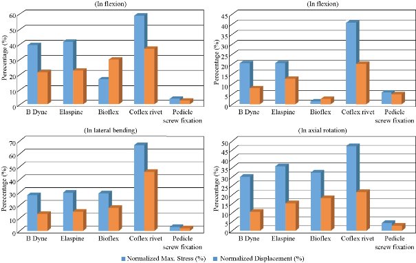
Fig. 10 Maximal von Mises stress of the disc intact model and total displacement of the spinal segment L4-L5 in flexion, extension, lateral bending and axial rotation for different devices of the rigid posterior fixation system and dynamic.
Maximal Von Mises stress at the disc annulus L4-L5
The highest maximum von Mises stress value for the IVD also appeared in Coflexe rivet model, with 1.0842 MPa in flexion, 0.47009 MPa in extension, 1.1316 MPa in lateral bending and 0.8263 MPa in axial rotation (Fig. 11). For the B Dyne model, maximum annulus stress at the surgical level (L5/L4) decreased remarkably by 39.22%, 20.60%, 27.86% and 30.12% in flexion, extension, torsion and lateral bending respectively, compared to the intact model (Fig. 10). For the Elaspine model, the maximum annulus stress at the surgical level decreased remarkably by 41,48%, 20,61%, 29,71%, and 36,05% in flexion, extension, torsion and lateral bending respectively, compared to the intact model. In the Bioflex model, the annulus stress decreased at the surgical L4/L5 level by 16,58%, 1,54%, 29,20% and 32,49% in flexion, extension, torsion and lateral bending respectively (Fig. 10). On the other hand, Fig. 10 clearly shows that with the Coflex rivet model, the maximum annulus stress at the surgical level decreased remarkably by 58,80%, 40,76%, 66,67% and 47,15% in flexion, extension, torsion and lateral bending respectively, compared to the intact model. Fig. 10 shows that the mixed loading (compression P plus bending moment (P1)) was applied to the upper surface of the lumbar vertebra L4 in the pedicle screw fixation model. The maximum annulus stress at the surgical level decreased remarkably by 3,70%, 5,91%, 2,99% and 4,35% in flexion, extension, torsion and lateral bending respectively, compared to the intact model.
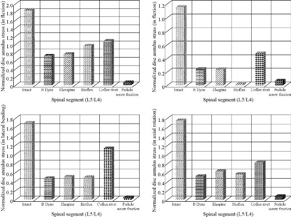
Fig. 11 Maximal von Mises stress of the disc annulus normalised to the intact model in flexion, extension, lateral bending and axial rotation. The B Dyne, Elaspine, Bioflex, pedicle screw fixation models decreased annulus stress at the surgical segment L4–L5 in flexion and extension. However, the annulus stress of the Coflex rivet decreased at the surgical segment in both lateral bending and axial rotation.
Stress distribution of the disc annulus (L5–L4)
Fig. 11 presents these contours for 5 models of fixation. Maximum displacement was revealed in the Coflex rivet model by the amount of 2.1477 mm in flexion, 0.58024 mm in extension, 2.6188 mm in lateral bending and 1.8423mm in axial rotation for the top anterior edge of the vertebral body due to the loading. Stress concentration and distribution pattern of the disc annulus at the surgical segment changed obviously in these models. In extension, the stress contour of the five models was concentrated on the posterior–superior regions of the disc annulus (Fig. 12). However, after implantation, the stress concentration of the disc annulus at the posterior disc diminished obviously. Furthermore, in flexion, the von Mises stress was concentrated on the anterior of the disc annulus regions, close to the superior and inferior sides of the endplate (Fig. 13). The Coflex rivet was found to have the most even disc annulus stress distribution in flexion, extension, lateral bending and axial rotation even when compared with the four posterior fixation system (B Dyne, Elaspine, Bioflex, pedicle screw fixation). In lateral bending and axial rotation, the equivalent stress was concentrated on the right part of the disc annulus regions, close to the superior and inferior sides of the endplate in the five models when compared with that of the intact model (Fig. 14 & 15). After implantation, the stress concentration of the disc annulus at the posterior disc was also diminished. Fig. 15 presents these contours for five models of fixation. In flexion and extension, the maximum total displacement revealed in Coflex rivet model was 36.81 mm, 20.15 mm for the top anterior edge of the vertebral body due to the loading. In lateral bending and axial rotation, the contour of total displacement in the Coflexe rivet model was 45.89 mm and 21.53 mm for the top anterior edge of the vertebral body due to the loading when compared with that of the intact model (Fig. 14 & 15). A finite element analysis on five models of fixation in order to stabilize L4-L5 motion segment was performed. Evaluated models were rigid and dynamic fixation systems. Maximum displacement for the whole of the motion segment was observed in Coflex rivet model. In flexion, the Bioflex model between 2 vertebrae permitted the complex to deflect up to 29.64 mm for the top anterior edge of the L4 vertebra. In flexion, the pedicle screw fixation model revealed relatively less displacement for the motion segment by 2.47 % reduction than the Coflex rivet model. Noticeably, higher fixation degree of pedicle screw fixation system was due to the straight rigid connector rod between the pedicle screws. In such a firm structure, a considerable share of the loading energy was consumed to bend the rigid rod. In RF model, the overall displacement of the motion segment was associated with the bending deflection of the straight rod. The B Dyne, Elaspine and Bioflex models, on the other hand, experienced higher displacement in comparison with pedicle screw fixation model. It may be confusing that how the two models (B Dyne and Elaspine) with an extra component of polymer-spacer (silicone) received higher movement of displacement; however, it was noticed that the stainless steel rigid connector rod in the pedicle screw fixation model was replaced by a rod with material of silicone which possessed the Young's modulus at approximately half of the RF rod’s. Thus, the overall resistance of the fixation system against the external flexion loading was remarkably diminished, and maximum displacement in the Coflexe rivet became 36.81% greater than in pedicle screw fixation model. Fundamental diversities in these five models led to different mechanic behaviors of the posterior fixation systems. In the pedicle screw fixation model, rigid rod resists against the loading and the exerted energy was devoted to bending the rod. In flexion, the two rods of Elaspine model were strained, but the anterior half of the rod of silicone were compressed and constrained by rising the movement of the motion segment. In Bioflex model, loading energy was consumed to compress or strain the spring ring; however, since the compression of the spring directly resulted in shortening of the ring's ends. in flexion, the overall displacement of the motion segment increased up to the maximum value of 1.59 mm. It should also be considered that characteristics of the spring provided in the connector rod in Bioflex model was of crucial importance in the results. Diameter of the rod, diameter of the ring, number of the rings and density of the rings per length could influence on the stiffness of such a design. After implantation, Maximum stress of the IVD also occurred in Coflex rivet model. Provision of the extreme movement for the motion segment resulted in increase of the stress at the anterior regions of the L4-L5 IVD. The maximum stress with these systems of fixation (1.13 MPa) was less than those reported in other numerical works. For instance, in flexion the maximum stress reported for Bioflex model by Zhang et al was roughly 0.96 MPa. It was then concluded that the loading was in medium range of load exertion of the human back based on an in-vivo experiment reporting that the human standing in relax sustained 0.5 MPa in the IVD for healthy individuals. In the present study, we also showed that the rivet connecting the metal wings and bony spinous process provided more security than the conventional device. Therefore, the rivet could improve load transmission on the posterior spinal structure to decrease the stress concentration on the disc annulus at the surgical segment in all motions. However, the Coflex rivet constrained the surgical segment in all motions and increased the displacement at the L4-L5 segments, especially in flexion. Therefore, the Coflex rivet increased annulus stress at L4-L5 segment both in flexion and in extension. Several assumptions were considered in the present numerical analysis. The most important one was to ignore the existence and roles of the muscles acting on vertebral bodies which could also resist the loading; however, since the goal was to compare the fixation systems, the analysis neglected them. Moreover, it should be taken into account that the loading was adopted from the experiment. Similar numerical simulations can elucidate the efficacy of such fixation systems in other cases as well.
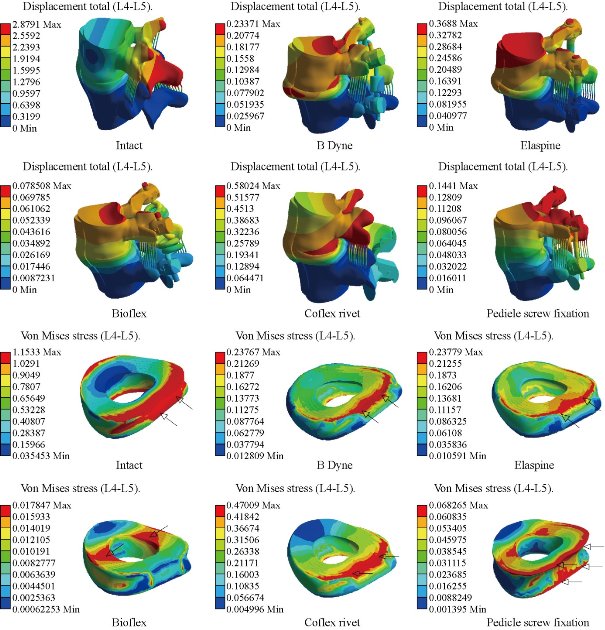
Fig. 12 Total displacement of the motion segment and von Mises stress distribution of the surgical segment L4–L5 disc annulus in extension for various surgical models. The stress of the intact and four models (B Dyne, Elaspine, Coflex rivet, pedicle screw fixation) was concentrated on the posterior–superior regions of the annulus. For the Bioflex model, the stress was concentrated on the left and right regions of the annulus, which were close to the superior and inferior sides of the endplate in the intact model. After implantation, the stress concentration of the disc annulus diminished obviously.
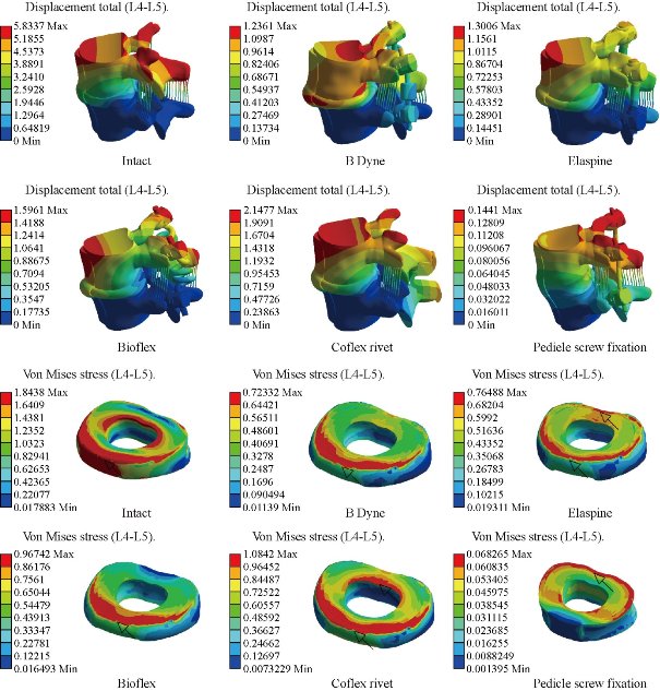
Fig. 13 Stress distribution of the surgical segment L4–L5 disc annulus in flexion for various surgical models. The stress was concentrated on the superior and inferior regions of the annulus, which were close to the superior and inferior sides of the endplate in the B Dyne and Bioflex models. For the Elaspine, Coflex rivet and pedicle screw fixation models the stress was concentrated at the posterior and anterior regions of the annulus, The Coflex rivet and Bioflex models had the most even disc annulus stress distribution.
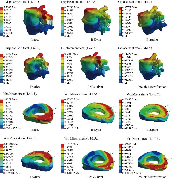
Fig. 14 Stress distribution of the surgical segment L4–L5 disc annulus in right lateral bending for various surgical models. The stress was concentrated on the right regions of the annulus, which were close to the superior and inferior sides of the endplate in the intact and defect models. The Coflex rivet model had the most even disc annulus stress distribution. After pedicle screw fixation, the stress concentration of the disc annulus diminished obviously.
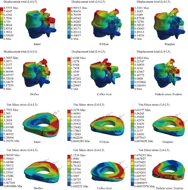
Fig. 15 Stress distribution of the surgical segment L4–L5 disc annulus in right axial rotation for various surgical models. The stress was concentrated at the right regions of the annulus, which were close to the superior and inferior sides of the endplate in the defect model. After implantation, the stress concentration of the disc annulus diminished obviously.
Conclusions
The finite element method (FEM) is a very precise technique used to analyze structural stresses. With its application in engineering, the method can solve many equations to calculate the stresses based on the mechanical properties of the structures being analyzed. FEM has many advantages highlighted by the possibility of including the heterogeneity and irregularity of the contour of the spine in the design of the model and the relative ease with which the loads can be applied to different directions and sizes for more complete analysis. The Coflex rivet implantation can provide stability in all motions and can reconstruct the posterior spinal structure for load sharing to reduce disc annulus stress at the surgical segment L4-L5. However, the Coflex rivet caused a higher displacement and stress at the disc. As a general conclusion, applications of the fixation systems can considerably reduce the load on the IVD and prepare conditions for the healing of injured IVD. Furthermore, dynamic modes of fixations, i.e. B Dyne, Elaspine, Bioflex and Coflex rivet, confer the possibility of movement to the motion segments in order to facilitate spinal activities.
Acknowledgements
The author kindly appreciates Mr. Said Kebdani and Smail Manssouri for their help in the model preparation. This paper has been done by personal expenses. All authors had equal role in the design, work, statistical analysis and manuscript writing.
References
Copyright© 2017 Samir Zahaf, Said Kebdani. This is an open-access article distributed under the terms of the Creative Commons Attribution License, which permits unrestricted use, distribution, and reproduction in any medium, provided the original author and source are credited.

|
Nano Biomedicine and Engineering. Copyright © Shanghai Jiao Tong University Press |
 |