Research Article
Numerical Study of the Effect of Rigid and Dynamic Posterior Attachment Systems on Stress Reduction in Cortical and Spongy Bones of the Lumbar Segments L4-L5
Said Kebdani 1 , Samir Zahaf 1*, Bensmaine Mansouri 1, Benaoumeur Aour 2
1 Laboratoire de Mécanique Appliquée, Département de Génie Mécanique, Université des Sciences et de la technologie d’Oran Mohamed Boudiaf, USTO-MB, BP 1505, El M’naouer, 31000 Oran, Algérie. (Laboratory of Mechanical Application, Department of Mechanical Engineering, University of Science and Technology of Oran Mohamed Boudiaf, USTO-MB, BP 1505, EL M’naouer, 31000, Oran, Algeria.)
2 Laboratoire de Biomécanique Appliquée et Biomatériaux, Ecole National Polytechnique d’Oran, BP 1523, EL M’naouer, 31000 Oran Algérie. (Laboratory of Biomedical Application and Biomaterials, National Polytechnique College of Oran, BP 1523, EL M’naouer, 31000 Oran Algérie.)
* Corresponding author. E-mail: samir.zehaf@univ-usto.dz or zahafsamir1983@gmail.com Tel.: +213-56131183 or +213-65954803
Received: Aug. 30, 2017; Accepted: Sep. 20, 2017; Published: Sep. 30, 2017
Citation: Said Kebdani, Samir Zahaf, Bensmaine Mansouri, and Benaoumeur Aour, Numerical Study of the Effect of Rigid and Dynamic Posterior Attachment Systems on Stress Reduction in Cortical and Spongy Bones of the Lumbar Segments L4 / L5. Nano Biomed. Eng., 2017, 9(3): 249-274.
DOI: 10.5101/nbe.v9i3.p249-274.
Abstract
Posterior instrumentation is a common fixation method used in the treatment of spinal diseases. However, the role of different models of fixation system in improving fixation stability in these fractures has not been established. Comparative investigation between posterior rigid fixation (pedicle screw) and four models of posterior dynamic fixation (B Dyne, Elaspine, Bioflex, Coflex rivet) may elucidate the efficacy of each design. The purpose of this study was to investigate the biomechanical differences between rigid fixation and dynamic fixation implantation by using finite element analyses. The goal of the present study was to evaluate the efficacy of five fixation systems mounted on L4-L5 motion segment. In this numerical study, finite element model of an L4-L5 segment was developed from computed tomography image datasets. Five fixation devices were also implanted internally to the motion segment. Another model with an intact intervertebral disc was also analysed for comparison. Loads simulating the physiological flexion, extension and lateral bindings were applied to the superior surface of L4. Results showed that the Elaspine, Bioflex, Coflex rivet and pedicle screw fixation implantation could provide stability in all motions and reduce von Mises stress in the cortical and spongy bone at the surgical segment L4-L5. Moreover, maximal von Mises stress in the annulus disc was observed in dynamic systems but within the safe range. The greater movement of the motion segment was also appeared in dynamic fixations. Existence of the fixation systems reduced the stress on the intervertebral disc which might be exerted in intact cases. Use of the fixation devices could considerably reduce the load on the discs and prepare conditions for healing of the injured ones. Furthermore, dynamic modes of fixation conferred the possibility of movement to the motion segments in order to facilitate the spinal activities. The numerical results showed that the posterior fixation system (rigid and dynamic) played a very important role in the absorption and minimization of stresses. On the other hand, the tow systems (rigid fixation and dynamic fixation) played such a great role in reducing the stress compared to other synthetic discs. In general, the posterior fixation system gave a lower level of stress in the cortical bones and the spongy bones of the L4-L5 lumbar segment compared to the intact model.
Keywords: Lumbar segment; Cortical; Spongy; Coflex rivet; B Dyne; Bioflex; Elaspine; Pedicle screw fixation; Annulus disc; Von Mises stress; Finite element analysis
Abbreviation: ALL = anterior longitudinal ligament; CL = capsular ligament; DF = dynamic fixation; DIV = intervertebral disc; FE = finite element; FEA = finite element analysis; FEM = finite element method; INT = intact; ISL = interspinous ligament; IVD = intervertebral disc; LF = ligamentum flavum; PLL = posterior longitudinal ligament; RF = rigid fixation; SED = strain energy density; SSL = supraspinous ligament; TL = transverse ligament
Introduction
Orthopaedic screws are primarily responsible for retaining the stability of most fracture fixation devices, and are commonly associated with failure due to pull-out associated with poor screw purchase or bone loss [1]. Screws are primarily used to supply necessary inter fragmentary compression, as standalone fixators and in conjunction with other orthopaedic hardware devices, particularly plates, and so their holding power within bone is crucial. Bones, on the other hand, are a dynamic connective tissue that gives form and support to the body, while protecting vital organs and facilitating locomotion. They also act as a reservoir for ions, especially for calcium and phosphate, the homeostasis of which is essential to life. These functions place serious require-ments on the mechanical properties of bones, which should be stiff enough to support the body's weight and tough enough to prevent easy fracturing. As well, bone must be resorbed and/or formed depending on the mechanical and biological requirements of the body. Bones, under normal physiological conditions, are an organ of optimal design, as they maintain both mechanical and chemical homeostasis. Bone remodelling activities serve to remove bone mass where the mechanical demands of the skeleton are low, for instance in the vicinity of orthopaedic implants, and form bone at those sites where mechanical loads are transmitted sufficiently [2]. After decades of research, the exact cause of cortical porosis around implants remains a subject of debate [3]. However, studies pertaining to bone–implant interactions have demonstrated that stress shielding, i.e. a reduction in normal mechanical loading of bones, can result in bone loss in the vicinity of implants [4, 5]. Direct observations of bone loss around screws prior to their avulsion have been shown by radiologic examination [6, 7]. Evidence of decreased compression at the bone–screw interface [8] has been hypothesized by Perren et al. [9] to be a result of abnormal bone remodeling. These findings suggest that normal bone remodeling will only persist if there is a constant supply of compression or mechanical stimuli transferred to the bone surrounding implants. In relation to implants, stiff metallic screws, with stiffness on the order of 100 - 200 GPa, carry the majority of the shared load. This unequal load sharing causes the softer adjacent bone, with stiffness on the order of 1 - 20 GPa [10], to be atrophied. This response acts in accordance with Wolff's law of functional adaptation, which states that “[e]very change in the form and function of a bone is followed by certain definite changes in their internal architecture and equally definite secondary alterations in their external conformation, in accordance with mathematical laws” [11]. The “biomechanical compatibility” of a particular screw with bone can therefore be characterized by the stress (or strain energy density (SED), or any other type of mechanical stimuli) distribution that develops in the bone around the screw. A loss of compression between implanted screws and bone is inevitable in vivo, particularly in the case of lag screws [8], and so implants should be designed in a manner that limits the stress shielding effect. Examining stress distributions in situ may shed some light on the effects of implant characteristics; however, which mechanical stimulus (stress, strain, strain rate, SED, etc.) is responsible for the initiation of the bone remodeling process is still an open question [12, 13]. Many researchers are in favor of SED and/or its rate as a mechanical stimulus for the initiation of bone remodeling process [12, 14–20]. Considering that stimuli transfer from implants is essential for bone remodeling, it is necessary to quantify and compare how altered implant parameters reflect upon stimuli distributions within bones. Pullout tests performed in vivo and in synthetic samples have shown that besides host material density [21], screw geometry also affects pullout strength [22–25]. While sufficient pullout strength is necessary to prevent screw avulsion, computational means such as finite element analysis (FEA) are invaluable for evaluating mechanical stimuli distributions in implant–bone constructs [26–28]. FEA allows for simulation of a variety of different implant parameters that have been shown to influence stress and strain distributions in neighboring bone [29–32]; however, most models do not systematically relate parameters to stress shielding effects. One example wherein stress shielding was quantified is the work by Gefen [26]. As a means of comparing the effect of screw parameters on stress shielding, Gefen used a ratio of resultant stress in bone to stress in adjacent screw threads during a compressive load. Although this research provided a means for quantifying potential stress shielding effects, it only considered one type of mechanical stimuli [26]. The primary goal of this research was to examine whether meaningful differences existed between the distributions of stress and SED in bones resulting from implant loading, which could ultimately determine the rate of bone remodeling and stress shielding in the neighboring bone. Here, FEA was employed to simulate a tensile load applied to an orthopedic screw inserted into bone. Considering that transfer of mechanical stimuli to the bone is necessary to prevent stress shielding, we systematically characterized the transfer of two types of mechanical stimuli from the screw to the surrounding bones, namely stress and strain energy densities. We considered a previously defined stress transfer parameter [26, 46], and proposed a newly defined criterion to evaluate SED transfer between an implanted screw and the adjacent bone. This new parameter allowed us to compare stimuli (SED and stress) transfer to bones resulting from changes in implant parameters. Comparing these distributions sheds light on which screw configurations may lead to greater transfer of mechanical stimuli to the neighboring bone, and which stimuli is a better candidate for investigating stress shielding in a bone–screw system. Although the efficacy of the fixation systems has been separately studied, no comparative study exists to shed light on the pros and cons of these systems in a fixed model that underwent the same conditions. Moreover, the measures of the efficiency of the fixation systems vary between stress/strain in IVD and vertebrae or the displacement of the motion segment. Therefore, the present investigation was aimed at comparing the prevalent models of spine fixations including rigid fixation (RF) and dynamic fixation (DF) systems in a same model of loading conditions using finite element method (FEM). The principal aim of the present study was to compare the provision of movement facility for the motion segment against reduction in the stress of intervertebral disc (IVD). Fig. 1 shows two vertebrae of the spinal column with an IVD under the effect of a compound loading (compression P + bending moment P1). The compressive load P created an internal pressure in the nucleus; this pressure would thereafter generate the disc degeneration or degenerative disc disease (Fig. 2). As regards the forward flexion P1, if the load P1 increased, automatically, the distance between the point of load application and the axis of the spinal column increased. We saw that the posterior portion of the annulus fibrosis was tensioned and the other front portion was compressed; that is to say, the nucleus pulposus bursted back (posterior compression); this compression produced by disc protrusion came into contact with a nerve root called the herniated disc.
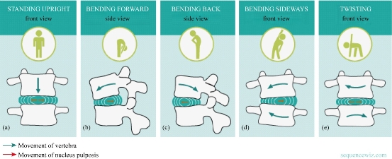
Fig. 1 The IVD with (a) compression, (b) flexion, (c) extension, (d) lateral bending and (e) axial rotation [6].
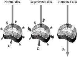
Fig. 2 Load distribution at the disc D1 according to its state [7].
Experimental
FE model of intact L4-L5 segment lumbar spine (intact (INT) model)
Three-dimensional model of an intact human L4 vertebra was constructed from computed tomography image datasets. The model was then adapted to form the L4-L5 lumbar segment, with an assumed IVD space of 11 mm. The vertebrae were treated as cortical bones throughout, with linear elastic isotropic material properties. The articular facets and the IVD were modelled as linear elastic isotropic material. The material properties of the components used in this study are presented in Table 1. The model was then imported to a standard finite element (FE) package and converted to tetrahedral elements for FEA. The completed model of the intact lumbar segment consisted of 32,7621 nodes and 199,689 elements (Fig. 3). The commercially available FE program, Ansys 16 (ANSYS Inc., Canonsburg, PA, USA), was used to model the spinal segments The FE model of the osseoligamentous lumbar segment included the vertebrae, one IVD, endplates, posterior elements and the following ligaments: supraspinous ligament (SSL), interspinous ligament (ISL), ligamentum flavum (LF), transverse ligament (TL), posterior longitudinal ligament (PLL), anterior longitudinal ligament (ALL) and capsular ligament (CL). The material properties of the intact L4-L5 segment were assumed to be homogeneous, and a detailed description has been presented in our previous studies [57, 58]. The ligaments were simulated using ten-node link elements with tension resistance only, and the elements were arranged in the anatomic orientation. ten-node solid elements were used for modelling of cortical bones, cancellous bones, endplates, posterior bony structures and discs. The annulus disc consisted of fibres embedded in the ground substance. Annular fibres in 6 layers were modelled using ten-node link elements with tension resistance only and placed in an anatomic orientation [59–61]. The facet joints were treated as nonlinear 3D contact pairs using surface-to-surface contact elements, and the coefficient of friction was set to 0.1 [57, 58]. The material properties of the INT model are listed in Table 1 and were chosen from previous studies [39–58]. All seven ligaments were simulated by ten node link elements with resistance tension only, and they were arranged in the anatomical direction given by the text book [54]; the cross-sectional area of each ligament was obtained from previous studies [47, 52–54]. A ten-node solid element was used for modeling the annulus ground substance. Cortical bones and cancellous bones were assumed to be homogeneous and isotropic. The IVD consisted of annulus ground substance and nucleus pulposus, which embeded collagen fibers in the ground substance. The nucleus pulposus was modeled as an incompressible fluid with bulk modulus of 1MPa by an ten-node fluid element [45–53]. The facet joint was treated as a sliding contact problem using surface-to-surface contact elements, and the coefficient of friction was set at 0.1 [55, 56].
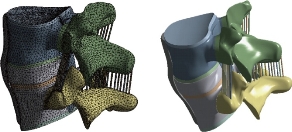
Fig. 3 FE model of the L4-L5 Motion Segment with IVD.
Table 1 Material properties used in the FE model.
|
Material |
Young modulus (E) (MPa) |
Poisson Coefficient |
References |
|
Cortical Bone |
12000 |
0.3 |
[39-45] |
|
Cancellous Bone |
100 |
0.2 |
[39, 41-42, 44-45] |
|
Posterior Bone |
3500 |
0.25 |
[39-41, 45-46] |
|
Cartilage Endplates |
12000 |
0.3 |
[40, 42, 47] |
|
Annulus Ground Substance |
4.2 |
0.45 |
[39-40, 42, 45, 49-50] |
|
Nucleus Pulposus |
1 |
0.499 |
[45, 48, 51-53] |
|
Anterior Longitudinal Ligament |
7.8 (<12%), 20.0 (>12%) |
0.3 |
[55, 56–58] |
|
Posterior Longitudinal Ligament |
10.0 (<11%), 20.0 (>11%) |
0.3 |
[55, 56–58] |
|
Ligamentum Flavum |
15.0 (<6.2%), 19.5 (>6.2%) |
0.3 |
[55, 56–58] |
|
Intertransverse Ligament |
10.0 (<18%), 58.7 (>18%) |
0.3 |
[55, 56–58] |
|
Supra-Spinous Ligament |
8.0 (<20%), 15.0 (>20%) |
0.3 |
[55, 56–58] |
|
Inter-Spinous Ligament |
10.0 (<14%), 11.6 (>14%) |
0.3 |
[55, 56–58] |
|
Capsular Ligament |
7.5 (<25%), 32.9 (>25%) |
0.3 |
[55, 56–58] |
FE model of bilateral B Dyne implant fixation implanted into the L4–L5 segment (B Dyne implant fixation model)
The existing geometrical model of the implant realized with CAO software (Solidworks 2016) was imported. It consisted of an assembly of five parts: The piston rod, the cylindrical body, the fixed rod, the ring and the damper block. The contact surfaces between the body and the fixed rod had a threaded area which made it possible to assemble the implant. In the manufacturing process, after assembly, these two parts were welded together. The geometry of these contact surfaces had therefore been simplified on the geometric model (Fig. 4) in order to facilitate the meshing and calculation steps. The metal parts (piston rod, cylindrical body and fixed rod) were modeled in titanium TA6V ELi with elastic properties, Young’s modulus and Poisson’s ratio were assigned to be 112,400 MPa and 0.34, respectively. The deformable parts (ring and damper block) are modeled with an elastic behavior of a silicone, Young’s modulus and Poisson’s ratio were assigned to be 600 MPa and 0.49. The model B Dyn consisted of 228,348 elements and 378,676 nodes (Fig. 4).
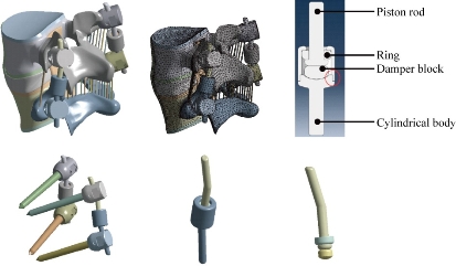
Fig. 4 FE model of the L4-L5 motion segment with posterior DF system B Dyne.
FE model of bilateral Elaspine implant fixation implanted into the L4–L5 segment (Elaspine implant fixation model)
The Elaspine implant consisted of six parts: four metal elements made of titanium alloy (Ti6Al4V ISO 5832-3) and two deformable rods made of polymer (silicone). A deformable rod was made of polymer (silicone) with a length of 60 mm and a diameter of 7 mm, which is mentioned in Fig. 5. The screw-bone interfaces were assigned to be fully constrained. The material used for the pedicle screws was Ti-6Al-4V. Young’s modulus and Poisson’s ratio were assigned to be 113,000 MPa and 0.3, respectively. The two deformable parts were modeled with an elastic behavior which contained a Young’s modulus and Poisson’s ratio that were assigned to be 600 MPa and 0.49. The model Elaspine consisted of 223,950 elements and 373,025 nodes (Fig. 5). An assembly of two rods and four screws (spinal assembly) was required to stabilize a spinal segment. Each implant was attached to the lumbar vertebrae using titanium pedicle screws (Fig. 5).
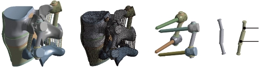
Fig. 5 FE model of the L4-L5 motion segment with posterior DF system Elaspine.
FE model of bilateral Bioflex implant fixation implanted into the L4–L5 segment (Bioflex implant fixation model)
The Bioflex implant was a helical spring manufactured by the company BioSpine, The total length of the rod was 70 mm and the spring height was 15.7 mm, The spring diameter was 5 mm and the pitch equalled 5.5 mm. The material used for the Bioflex model was Ti-6Al-4V. Young’s modulus and Poisson’s ratio were assigned to be 113,000 MPa and 0.3, respectively. The Bioflex model consisted of 228,101 elements and 399,240 nodes (Fig. 6).
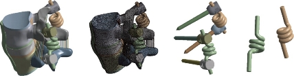
Fig. 6 FE model of the L4-L5 motion segment with posterior DF system Bioflex.
FE model of Coflex rivet implanted into the L4–L5 segment (Coflex rivet model)
The Coflex rivet model was implanted at the L4–L5 segment; this model was used to simulate instability by cutting the LF, the facet capsules and 50% of the inferior bony facet bilaterally at the L4–L5 segment (Tsai et al. 2006; Kettler et al. 2008). In addition, the SSLs and ISLs had to be resected before insertion. The Coflex rivet differed from the original Coflex implant by adding two rivets joining the wings and spinous processes (Fig. 7). The coefficient of friction for the rest of the contact regions was set to 0.1 (Fig. 6). The rivets were simplified as cylinders and were constrained to both the holes on the wings of the Coflex and the spinous processes in all degrees of freedom. (The degrees of freedom of screw nodes were interpolated with the corresponding degrees of freedom of the nodes on the Coflex and spinous processes during the execution of ANSYS program.) The material used for the Coflex rivet was a Ti-6Al-4V alloy. The Young’s modulus and Poisson’s ratio were assigned to be 113,000 MPa and 0.3, respectively. The model Coflex rivet consisted of 202,615 elements and 332,396 nodes (Fig. 7).
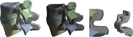
Fig. 7 FE model of the L4-L5 motion segment with posterior DF system Coflex rivet.
FE model of bilateral pedicle screw fixation implanted into the L4–L5 segment (pedicle screw fixation model)
The pedicle screw fixation model was implanted at the L4–L5 segment. The difference between the pedicle screw fixation model and the abovementioned implantation models was that the pedicle screw fixation model preserved the SSLs and ISLs (Fig. 8). The pedicle screw fixation consisted of two rods (diameter, 5 mm) and four pedicle screws (diameter, 5 mm). The pedicle screws were inserted through the pedicles of the L4 and L5 vertebrae bilaterally. The pedicle screws were simplified as cylinders. The screw-bone interfaces were assigned to be fully constrained. The material used for the pedicle screws was Ti-6Al-4V. Young’s modulus and Poisson’s ratio were assigned to be 113,000 MPa and 0.3, respectively. The model pedicle screw consisted of 225,769 elements and 394,288 nodes (Fig. 8). Therefore, the purpose of this work was to study the effect of rigid and dynamic posterior attachment systems on stress reduction in cortical and spongy bones of the lumbar segment L4-L5 between the RF and DF systems of the spinal column by using FEA on a two-segment spinal model. In addition, comparative investigation between the RF and the four DF systems may elucidate the efficacy of each design. The goal of the present study was to evaluate the efficacy of four fixation systems mounted on L4-L5 motion segment. FEM was used to evaluate stress distribution in the disc and determine the overall displacement of the segment as a measure of movement possibility, the maximal von Mises stress at the annulus disc and the von Mises stress distribution at the surgical annulus disc.
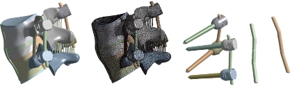
Fig. 8 FE model of the L4-L5 Motion Segment with posterior DF system pedicle screw fixation.
Boundary and loading conditions
The loading condition was similar to the in-vitro study of Yamamoto et al., in which the intact L4-L5 segment was subjected to the maximum possible load without causing spinal injury [33]. Therefore, all four physiological motions were imposed, each with a moment P1 equal to 10.6 Nm and a compression P equal to 400 N on the superior surface of the L4 level. These models constrained all degrees of freedom at the inferior surfaces of the vertebra L5. Fig. 9 shows the location of the applied loads.
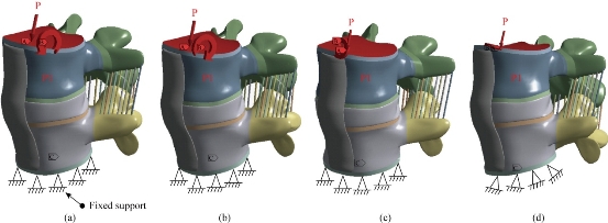
Fig. 9 Biomechanical models of the intact L4-L5 segment: (a) Anterior load (flexion); (b) Posterior load (extension); (c) Lateral load (flexion lateral); and (d) Axial load (torsion).
Results and Discussion
Maximal von Mises stress of the cortical bones of the spinal segment L4-L5
Fig. 10 shows the maximal von Mises stress of the cortical bones of the spinal segment L4-L5 in flexion, extension, lateral bending and axial rotation for different devices of posterior RF and DF fixation systems. The B Dyne, Bioflex, Coflex rivet, pedicle screw fixation models increased von Mises stress at the surgical segment L4–L5 in flexion, lateral bending and axial rotation. However, the Elaspine model decreased von Mises stress at the surgical segment in flexion, lateral bending and axial rotation. On the other hand, Fig. 11 shows that the maximum of von Mises stress in the cortical bones L5 and L4 equalled to 19.295, 10.996, 19.925, 11.645 MPa and 10.88, 10.996, 14.921, 21.024 Mpa, respectively to the other components of the spinal segment system. Fig. 12 shows that the implantation of the lumbar segment L4-L5 with the dynamic posterior fixation system B Dyne inserted between the vertebra L4 and L5 and simulated by the FEM confirmed an increase of the equivalent stress in the cortical bones L5 and L4. In flexion, we noted in Fig. 11 and 12 that the von Mises stress in the cortical bones L5 and L4 increased to 19.295, 31.176 MPa and 10.88, 13.249 MPa. Fig. 12 shows that for the extension load, the two FE models, INT model and B Dyne supported maximal von Mises stress equal to 10.996, 10.701 MPa and 10.996, 23.559 MPa in the cortical bones L4 and L5 with respect to the other components of the spinal segment system in lateral bending and axial rotation, The B Dyne increased von Mises stress at the cortical bones L4 and L5 of the surgical segment L4–L5, which justified that the dynamic posterior fixation system B Dyne did not play a very important role in stabilizing the movement of the spine.
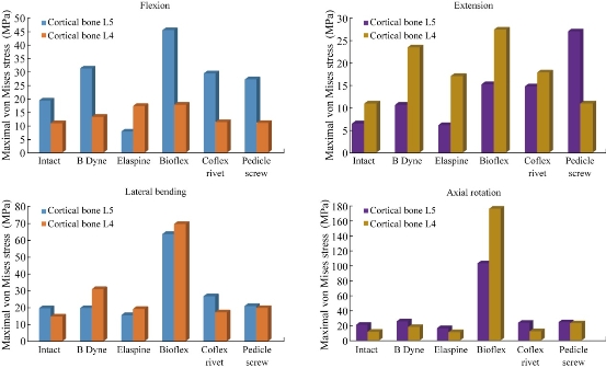
Fig. 10 Maximal von Mises stress of the cortical bones of the spinal segment L4-L5 in flexion, extension, lateral bending and axial rotation for different devices of posterior RF and DF systems.
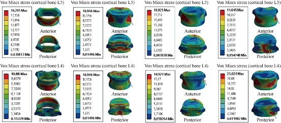
Fig. 11 Von Mises stress distribution of the cortical bones L4 and L5 to the INT model in flexion, extension, lateral bending and axial rotation. The stress was concentrated at the anterior and posterior regions of the cortical bones L4 and L5 of the lumbar segment L4-L5, which were close to the superior and inferior sides of the endplate in flexion and extension. For lateral bending load, the stress was concentrated at the right regions of the cortical bones of the lumbar segment L4-L5. For axial rotation load, the stress was concentrated at the anterior and posterior regions of the cortical bones of the lumbar segment L4-L5 (outline in red). For the two loads of lateral bending and axial rotation, lumbar segment L4-L5 had the most even cortical bones stress distribution.
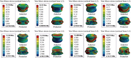
Fig. 12 Von Mises stress distribution of the cortical bones L4 and L5 to the B Dyne model in flexion, extension, lateral bending and axial rotation. The stress was concentrated at the anterior and posterior pedicle regions of the cortical bones L4 and L5 of the lumbar segment L4-L5, which were close to the superior and inferior sides of the endplate in flexion and extension. For lateral bending load, the stress was concentrated at the anterior and right pedicle regions of the cortical bones of the lumbar segment L4-L5. For axial rotation load, the stress was concentrated at the anterior and posterior pedicle regions of the cortical bones of the lumbar segment L4-L5 (contour in red). For the two loads of flexion and lateral bending, lumbar segment L4-L5 had the most even cortical bone stress distribution.
Maximal von Mises stress at the cortical bones of L4-L5 to Elaspine model
Fig. 13 shows that the mixed loading, compression P plus bending moment P1, presented a contour of the maximal stress (red part) in the cortical bone of L4-L5. We saw in this figure the stress was concentrated at the anterior and posterior pedicle regions of the cortical bone of the lumbar segment L4-L5, which were close to the superior and inferior sides of the endplate in flexion and extension. A loading applied to the upper surface of the lumbar vertebra L4 of the spine caused a high concentration of the maximal von Mises stress at the anterior and posterior parts of the cortical bones of L5 and L4 (red part) which equalled to 25.677 and 17,31 MPa (Fig. 13). For extension, lateral bending and axial rotation load, the implantation of the lumbar segment L4-L5 with the dynamic posterior fixation system Elaspine inserted between the vertebrae L4-L5 and simulated by the FEM confirmed a decrease of the equivalent stress in the cortical bone of L4-L5 which equaled to 6.1576, 17.145, 15.737, 19.503, 16,449 and 11,034 MPa. In flexion, we noted in Fig. 11 and 13 that the von Mises stress at the cortical bone of L5 and L4 increased to 19.295, 31.176 Mpa and 10.88, 13.249 Mpa, which justified that the dynamic posterior fixation system Elaspine played a very important role in stabilizing the movement of the spine in extension, lateral bending and axial rotation.
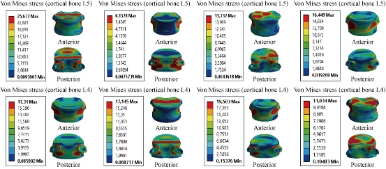
Fig. 13 Von Mises stress distribution of the cortical bone of L4-L5 to Elaspine model in flexion, extension, lateral bending and axial rotation. The stress was concentrated at the anterior and posterior pedicle regions of the cortical bone of the lumbar segment L4-L5, which were close to the superior and inferior sides of the endplate in flexion and extension. For lateral bending load, the stress was concentrated at the anterior and right pedicle regions of the cortical bone of the lumbar segment L4-L5, For axial rotation load, the stress was concentrated at the anterior surface of the cortical bone L5 and superior surface of the cartilage endplates of the cortical bone of L4 (contour in red). For the flexion and lateral bending loads applied to lumbar segment L4-L5, there existed the most even cortical bone stress distribution.
Maximal von Mises stress at the cortical bones of L4-L5 to Bioflex model
Fig. 14 shows von Mises stress distribution of the cortical bone of L4-L5 to Bioflex model in flexion, extension, lateral bending and axial rotation. The stress was concentrated at the anterior and posterior regions of the cortical bone of the lumbar segment L4-L5, which were close to the superior and inferior sides of the endplate in flexion and extension. For lateral bending load, the stress was concentrated at the posterior and right regions of the cortical bone of L4 and the anterior and superior surface of the cortical bone of L5. For axial rotation load, the stress was concentrated at the posterior surface of the cortical bone of L4 and the superior surface of the cartilage endplates of the cortical bone of L5 (red part). For the lateral bending and axial rotation loads applied to lumbar segment L4-L5, there existed the most even cortical bone stress distribution. On the other hand, Fig. 14 shows that the dynamic posterior fixation system Bioflex inserted between the two segments of L4-L5 absorbed maximal von Mises stress which equalled to 45.445, 27,551, 70,852 and 177,5 MPa in the cortical bone of L4, and which equalled to 45.445, 15.306, 64.753 and 103.95 MPa in the cortical bone of L5, with respect to the other compounds of the spinal segment L4-L5 (contour in red). Hence, the replacement of the dynamic posterior fixation system Bioflex did not play a very important role in reducing stress (Fig. 14).
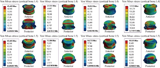
Fig. 14 Maximal von Mises stress at the cortical bones of L4-L5 to Bioflex model
Maximal von Mises stress at the cortical bones of L4-L5 to Coflex rivet model
Fig. 15 shows the dynamic posterior fixation system Coflex rivet inserted in the two segments of L4-L5, The instrumented model was subjected to a compression load P with the bending moment P1, on the four physiological planes (flexion, extension, lateral bending and axial rotation). The results showed that the maximal von Mises stress in the cortical bones of L4 and L5 equalled to 11.303, 17.962, 17.435 and12.226 MPa, and 29.368, 14.846, 27.173 and 23.727 MPa (contour in red). We concluded that the implantation of the Coflex rivet decreased von Mises stress at the cortical bone of L4-L5 in flexion and axial rotation and increased in extension and lateral bending; that is to say, the Coflex rivet could ensure the stability of the movements in flexion and axial rotation, and could reconstruct the posterior vertebral structure for the sharing of loads in order to reduce the annular stress at the surgical segment.
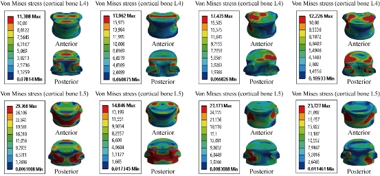
Fig. 15 Von Mises stress distribution of the cortical bone of L4-L5 to the Coflex rivet model in flexion, extension, lateral bending and axial rotation. The stress was concentrated at the superior surface endplate of the cortical bone of L4 and posterior pedicle regions of the cortical bone of L4, and at the anterior and posterior surface of the cortical bone of L5 which were close to the superior and inferior sides of the endplate in flexion and extension. For lateral bending load, the stress was concentrated at the superior and right regions of the cortical bone of L4, and the anterior and posterior pedicle surface of the cortical bone of L5. For axial rotation load, the stress was concentrated at the posterior and superior surface of the cortical bone of L4, and the anterior and posterior pedicle surface of the cartilage endplates of the cortical bone of L5 (red part). For the flexion and lateral bending loads applied to lumbar segment L4-L5, there existed the most even cortical bone stress distribution.
Maximal von Mises stress at the cortical bone of L4-L5 to the pedicle screw fixation model
Fig. 16 shows the posterior RF system (pedicle screw fixation) inserted between the lumbar segment L4-L5. The model was fixed at the bottom of L5 and loaded at the top of L4 to simulate flexion, extension and lateral bending. The results showed that pedicle screw fixation decreased von Mises stress in the cortical bones of L4 and L5, which equalled to 11.009 and 27.186 MPa in flexion (contour in red). On the other hand, for extension, lateral bending and axial rotation, the posterior RF system increased von Mises at the cortical bone of L4-L5; that is to say, pedicle screw fixation could ensure the stability of the movements in flexion and could reconstruct the posterior vertebral structure for the sharing of the loads in order to reduce the annular stress at the surgical segment.
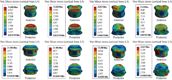
Fig. 16 Von Mises stress distribution of the cortical bone of L4-L5 to pedicle screw fixation model in flexion, extension, lateral bending and axial rotation. The stress was concentrated at the superior surface endplate of the cortical bone of L4-L5, and anterior regions of the cortical bone of the lumbar segment L4-L5, which were close to the superior and inferior sides of the endplate in flexion and extension. For lateral bending load, the stress was concentrated at the superior and right regions of the cortical bone of L4, and the superior and inferior surface endplate of the cortical bone of L5. For axial rotation load, the stress was concentrated at the posterior pedicle and superior surface of the cortical bone of L4, and the anterior and posterior pedicle surface of the cartilage endplates of the cortical bone of L5 (red part). For the flexion and extension loads applied to the lumbar segment L4-L5, there existed the most even cortical bone stress distribution.
Maximal von Mises stress at the cancellous bone of the spinal segment L4-L5
Fig. 17 shows the maximal von Mises stress at the cancellous bone of the spinal segment L4-L5 in flexion, extension, lateral bending and axial rotation for different devices of posterior RF and DF systems. The B Dyne, Elaspine, Bioflex, Coflex rivet and pedicle screw fixation models decreased von Mises stress at the cancellous bone of L4. But the two models of dynamic posterior fixation systems, B Dyne and Elaspine, increased von Mises stress at the cancellous bone of L5 in flexion. For the load extension, the B Dyne, Elaspine, Bioflex, Coflex rivet decreased the von Mises stress at the cancellous bone of L5. The posterior RF system, pedicle screw fixation, increased the von Mises stress at the cancellous bone of L5. The Elaspine, Bioflex, Coflex rivet, pedicle screw fixation decreased von Mises stress at the spongy bone of L4, and von Mises stress increased at the dynamic posterior fixation system B Dyne. However, Elaspine, Bioflex, Coflex rivet and pedicle screw fixation decreased von Mises stress at the spongy bone of L4-L5. The B Dyne increased von Mises stress at the surgical segment L4-L5 in lateral bending and axial rotation. Fig. 18 shows the stress distribution of the cancellous bone of L4-L5 under four different loading conditions: extension, flexion, lateral bending and axial rotation. In all cases, the INT model showed the maximal von Mises stress at the cancellous bone of L4 equalled to 1.0172, 0.7565, 0.5676 and 0.3910 MPa, and at L5 equalled to 0.5476, 0.2063, 0.4294 and 0.3020 MPa, respectively to the other components of the spinal segment system. Concerning the flexion load, Fig. 19 shows the implantation of the lumbar segment L4-L5 with the dynamic posterior fixation system B Dyne inserted between the lumbar segment L4-L5, and the FEM confirmed a decrease of von Mises stress at the cancellous bone of L4-L5. With B Dyne model under tow loading physiology (lateral bending and axial rotation), von Mises stress at the cancellous bones of L5 and L4 increased to 0.9164, 0.6331 Mpa and 0.6180, 0.7691 Mpa, respectively to the other components of the spinal segment system.
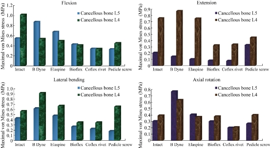
Fig. 17 Maximal von Mises stress at the cancellous bone of the spinal segment L4-L5.
Maximal von Mises stress at the cancellous bones of L4 and L5 to the INT model
Fig. 18 shows von Mises stress distribution at the cancellous bones of L4-L5 to the INT model in flexion, extension, lateral bending and axial rotation. The stress was concentrated at the anterior and posterior regions of the spongy bones of the lumbar segment L4-L5, which were close to the superior and inferior sides of the endplate in flexion and extension. For the lateral bending load, the stress was concentrated at the right regions of the spongy bone of the lumbar segment L4-L5. For axial rotation load, the stress was concentrated at the left regions of the spongy bone of the lumbar segment L4-L5 (contour in red). For the flexion and extension loads applied to the lumbar segment L4-L5, there existed the most even cancellous bone stress distribution.
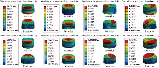
Fig. 18 Maximal von Mises stress at the cancellous bones of L4-L5 to the INT model.
Maximal von Mises stress at the cancellous bones of L4-L5 to the B Dyne model
Fig. 19 shows the von Mises stress distribution at the cancellous bones of L4-L5 to the B Dyne model in flexion, extension, lateral bending and axial rotation. Von Mises stress was concentrated at the anterior surface of the spongy bone of L4, and located at the upper and lower surface of the endplate of the cancellous bones of L4-L5 in flexion and extension. For the lateral bending load, the stress was concentrated at the right regions of the spongy bone of L4, the anterior surface of the spongy bone of L5, and was located at the superior surface of the endplate of the cancellous bone of L5. For axial rotation loads, the stress was concentrated in the posterior regions of the spongy bones of L4 and L5, and located at the superior surface of the spongy bones of L4 and L5 (contour in red). For the flexion and lateral bending loads applied to the lumbar segment L4-L5, there existed the most even cancellous bone stress distribution.
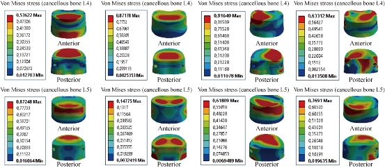
Fig. 19 Maximal von Mises stress at the cancellous bones of L4-L5 to B Dyne model.
Maximal von Mises stress at the cancellous bones of L4 and L5 to Elaspine model
Fig. 20 shows that von Mises stress was concentrated at the anterior surface of the spongy bone of L4, and located at the superior and inferior surface of the endplate of the cancellous bones of L4 and L5 in flexion and extension. On the other hand, the dynamic posterior fixation system, Elaspine model, decreased von Mises stress at the spongy bones of L4 and L5 which equalled to 0.4948, 0.7530, 0.3698 Mpa, and 0.6758, 0.1048, 0.4060 Mpa, respectively to the other components of the spinal segment system. In lateral bending, Elaspine model increased von Mises stress at the spongy bones of L4 and L5, which justified that the dynamic posterior fixation system Elaspine played a very important role in stabilizing the movement of the spine.
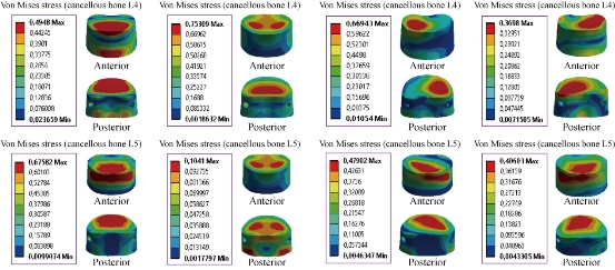
Fig. 20 Von Mises stress distribution of the cancellous bones of L4 and L5 to Elaspine model in flexion, extension, lateral bending and axial rotation. Von Mises stress was concentrated at the anterior surface of the spongy bone of L4, and located at the superior and inferior surface of the endplate of the cancellous bones of L4 and L5 in flexion and extension. For the lateral bending load, the stress was concentrated at the right regions of the spongy bone of L4, the anterior surface of the spongy bone of L5, and located at the superior surface of the endplate of the cancellous bone of L5. For axial rotation loads, the stress was concentrated in the superior regions of the spongy bones of L4 and L5, and located at the anterior surface of the spongy bone of L5 (contour in red). For the flexion, extension and lateral bending loads applied to the lumbar segment L4-L5, there existed the most even cancellous bone stress distribution.
Maximal von Mises stress at the cancellous bone of L4-L5 to Bioflex model
Fig. 21 shows the von Mises stress distribution of the cancellous bones of L4 and L5 to Bioflex model in flexion, extension, lateral bending and axial rotation. Von Mises stress was concentrated at the anterior surface of the spongy bone of L4, and located at the upper and lower regions of the endplate of the cancellous bones of L4 and L5 in flexion and extension (contour in red). For the lateral bending load, the stress was concentrated in the right regions of the spongy bone of L4 and the anterior surface of the spongy bone of L5, and located at the superior surface of the endplate of the cancellous bone of L5. For axial rotation loads, the stress was concentrated in the superior regions of the spongy bones of L4 and L5, and located at the anterior surface of the spongy bone of L5 (red part). For the flexion and axial rotation loads applied to the lumbar segment L4-L5, there existed the most even cancellous bone stress distribution. For the dynamic posterior fixation system, Bioflex model, the maximal von Mises stress at the segments surgical level L4-L5 decreased remarkably at the spongy bones of L4 and L5, and were equal to 0.4084, 0.3284, 0.3484, 0.3787 MPa, and 0.4250, 0.0830, 0.2673, 0.2991 MPa in flexion, extension, torsion, and lateral bending, respectively, compared to INT model (Fig. 21).
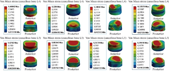
Fig. 21 Maximal von Mises stress at the cancellous bones of L4-L5 to Bioflex model.
Maximal von Mises stress at the cancellous bones of L4 and L5 to Coflex rivet model
Moreover, the stress concentration and distribution pattern changed more obviously at the segments lumbar L4-L5 in Coflex rivet model: Von Mises stress was concentrated at the anterior surface of the spongy bone of L4, and located at the upper and lower regions of the endplate of the cancellous bones of L4 and L5 in flexion and extension (contour in red). For the lateral bending load, the stress was concentrated in the right regions of the spongy bones of L4 and L5, and located at the superior surface of the endplate of the cancellous bones of L4 and L5. For axial rotation loads, the stress was concentrated in the superior regions of the spongy bones of L4 and L5, and located at the anterior surface of the spongy bone L5 (red part). For theflexion and lateral bending applied to the lumbar segment L4-L5, there existed the most even cancellous bone stress distribution. For the dynamic posterior fixation system (Coflex rivet model), the maximal von Mises stress at the segments surgical level L4-L5 decreased remarkably at the spongy bones of L4 and L5 which equalled to 0.3366, 0.3382, 0.3483, 0.2079 MPa, and 0.3393, 0.0782, 0.2242, 0.2027 MPa in flexion, extension, torsion and lateral bending, respectively, compared to INT model (Fig. 22).
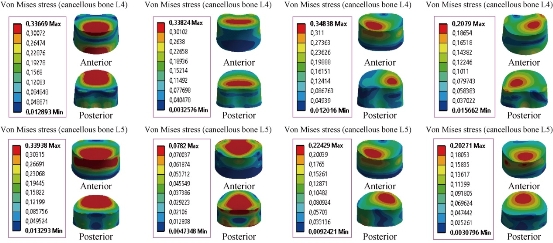
Fig. 22 Von Mises stress distribution of the cancellous bones of L4 and L5 to Coflex rivet model in flexion, extension, lateral bending and axial rotation. Von Mises stress was concentrated at the anterior surface of the spongy bone of L4, and located at the upper and lower regions of the endplate of the cancellous bones of L4 and L5 in flexion and extension (contour in red). For the lateral bending load, the stress was concentrated in the right regions of the spongy bones of L4 and L5 and located at the superior surface of the endplate of the cancellous bones of L4 and L5. For axial rotation loads, the stress was concentrated in the superior regions of the spongy bones of L4 and L5 and located at the anterior surface of the spongy bone of L5 (red part). For the flexion and lateral bending applied to the lumbar segment L4-L5, there existed the most even cancellous bone stress distribution.
Maximal von Mises stress at the cancellous bones of L4 and L5 to pedicle screw fixation model
For the posterior RF system (pedicle screw fixation) inserted between the lumbar segment L4-L5, the model was fixed at the bottom of L5 and loaded at the top of L4 to simulate flexion, extension and lateral bending. The results showed that pedicle screw fixation reduced von Mises stress in the cortical bones of L4 and L5, and equalled to 0.4503, 0.4503, 0.6551, 0.3986 MPa, and 0.33.2, 0.3302, 0.1816, 0.2652 MPa in flexion, extension, lateral bending and axial rotation (contour in red) (Fig. 23).
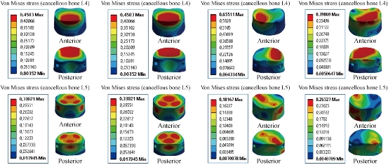
Fig. 23 Von Mises stress distribution of the cancellous bones of L4 and L5 to pedicle screw fixation model in flexion, extension, lateral bending and axial rotation. Von Mises stress was concentrated at the superior surface of the spongy bones of L4 and L5, and located at the upper regions of the endplate of the cancellous bones of L4 and L5 in flexion and extension (contour in red). For the lateral bending load, the stress was concentrated in the right regions of the spongy bones of L4 and L5, and located at the superior surface of the endplate of the cancellous bones of L4 and L5. For axial rotation loads, the stress was concentrated in the superior regions of the spongy bones of L4 and L5, and located at the anterior surface of the spongy bones of the lumbar segment L4-L5 (red part). For the flexion, extension and lateral bending loads applied to the lumbar segment L4-L5, there existed the most even cancellous bone stress distribution.
Maximal von Mises stress at the annulus disc of L4-L5
Fig. 24 shows the maximal von Mises stress at the annulus disc to the INT model in flexion, extension, lateral bending and axial rotation. The B Dyne, Elaspine, Bioflex, pedicle screw fixation models reduced annulus stress at the surgical segment L4–L5 in flexion, extension, lateral bending and axial rotation. However, the Coflex rivet reduced annulus stress at the surgical segment in flexion, extension, lateral bending and axial rotation. The two principal functions of the fixation systems were to balance the stabilization and dynamization of the motion segment, and to reduce the over-pressure on vulnerable tissues like muscles or IVDs. Therefore, overall displacement of the motion segment and stress at the IVD could be considered as measures for efficacy of the fixation systems.
Maximal von Mises stress at the disc INT model and total displacement of the spinal segment L4-L5
Fig. 25 presents the contours for five models of fixation. Maximal displacement was revealed in Coflex rivet model, as of 2.1477 mm in flexion, 0.58024 mm in extension, 2.6188 mm in lateral bending and 1.8423 mm in axial rotation for the top anterior edge of the vertebral body due to the loading. The highest maximal von Mises stress value for the IVD also appeared in Coflex rivet model, as of 1.0842 MPa in flexion, 0.47009 MPa in extension, 1.1316 MPa in lateral bending and 0.8263 MPa in axial rotation (Fig. 24). In flexion, the total displacement of the spinal segment L4-L5 decreased by 36.81% in Coflex rivet model, 29.64% in Bioflex model, 22.29% in Elaspine model, 21.18% in B Dyne model and 2.47% in pedicle screw fixation (Fig. 25). On the other hand, the maximal von Mises stress at the spinal segment L4-L5 decreased by 58.80% in Coflex rivet model, 41.48% in Elaspine model, 39.22% in B Dyne model, 16.58% in Bioflex model and 3.70% in pedicle screw fixation. However, the total displacement of the spinal segment L4-L5 and the maximal von Mises stress at the intact disc increased by 36.81%, 58.80% in Coflex rivet model, and 2.47%, 3.70% in pedicle screw fixation model at both L4 and L5 segments. In extension, the total displacement of the spinal segment L4-L5 decreased by 20.15% in Coflex rivet model, 12.80% in Elaspine model, 8.11% in B Dyne model, 5% in pedicle screw and 2.72% in Bioflex model at the surgical segment (Fig. 25). After implantation, von Mises stress effectively decreased by 40% in Coflex rivet mode, 20.61% in Elaspine model, 20.60% in B Dyne model, 5.91% in pedicle screw fixation model and 1.54% in Bioflex model when compared with the INT model. In addition, the von Mises stress was equal in the two dynamic models of B Dyne and Elaspine, but the total displacement of the spinal segment L4-L5 increased by 12.80% in Elaspine model and decreased by 8.11% in B dyne model at both L4 and L5 segments (Fig. 25). In lateral bending, the total displacement of the spinal segment decreased by 45.89% in Coflex rivet model, 17.88% in Bioflex model, 15.02% in Elaspine model, 13.18% in B Dyne model and 1.97% in pedicle screw fixation model at the surgical segment, when compared with that of the INT model (Fig. 25). However, von Mises stress in the intact disc decreased by 66.67% in Coflex rivet, 29.71% in Elaspine model, 29.20% in Bioflex model, 27.86% in the B dyne model, 2.99% in pedicle screw fixation model at both the L4–L5 segment (Fig. 25). In axial rotation, the anterior displacement of the spinal segment (L5/L4) decreased by 21.53% in Coflex rivet model, 18.24% in Bioflex model, 15.31% in Elaspine model, 10.57% in B Dyne model and 2.83% in pedicle screw fixation model at the surgical segment, when compared with that of the INT model. However, in pedicle screw fixation model, von Mises stress decreased by 4.35% at the L4–L5 segment and increased by 30.12% in B Dyne model, 32.49% in Bioflex model, 36.05% in Elaspine model and 47.15% in Coflex rivet at the adjacent L4–L5 segment (Fig. 25). For B Dyne model, maximal annulus stress at the surgical level L4-L5 decreased remarkably by 39.22%, 20.60%, 27.86% and 30.12% in flexion, extension, torsion and lateral bending respectively, compared to the INT model (Fig. 25). For Elaspine model, the maximal annulus stress at the surgical level decreased remarkably by 41.48%, 20.61%, 29.71% and 36.05% in flexion, extension, torsion and lateral bending respectively, compared to the INT model. In Bioflex model, the annulus stress decreased at the surgical level L4-L5 by 16.58%, 1.54%, 29.20% and 32.49% in flexion, extension, torsion and lateral bending, respectively (Fig. 25). On the other hand, Fig. 25 clearly shows that for Coflex rivet model, the maximal annulus stress at the surgical level decreased remarkably by 58.80%, 40.76%, 66.67% and 47.15% in flexion, extension, torsion and lateral bending respectively, compared to the INT model. Fig. 25 shows that with the mixed loading of compression P plus bending moment P1 applied to the upper surface of the lumbar vertebra L4 in Pedicle screw fixation, the maximal annulus stress at the surgical level decreased remarkably by 3.70%, 5.91%, 2.99% and 4.35% in flexion, extension, torsion and lateral bending respectively, compared to the INT model. Stress concentration and distribution pattern of the annulus disc at the surgical segment changed obviously in these models. In extension, the stress contour of the five models was concentrated at the posterior–superior regions of the annulus disc (Fig. 26). However, after implantation, the stress concentration of the annulus disc at the posterior disc diminished obviously. Furthermore, in flexion, von Mises stress was concentrated at the anterior regions of the annulus disc, close to the superior and inferior sides of the endplate (Fig. 26). Coflex rivet was found to present the most even annulus disc stress distribution in flexion, extension, lateral bending and axial rotation even when compared with the four posterior fixation systems B Dyne, Elaspine, Bioflex and pedicle screw fixation. In lateral bending and axial rotation, equivalent stress was concentrated at the right part of the annulus disc regions, close to the superior and inferior sides of the endplate in the five models when compared with that of the INT model (Fig. 26). After implantation, the stress concentration of the annulus disc at the posterior disc was also diminished. Fig. 25 presents these contours for five models of fixation. In flexion and extension, the maximal total displacement was revealed in Coflex rivet model as of 36.81 mm and 20.15 mm for the top anterior edge of the vertebral body due to the loading. In lateral bending and axial rotation, the contour of total displacement was concentrated at Coflex rivet model as of 45.89 mm and 21.53 mm for the top anterior edge of the vertebral body due to the loading when compared with that of the INT model (Fig. 29 & 30). Fig. 27 shows the total displacement at the motion segment and von Mises stress distribution at the annulus disc of the surgical segment L4–L5 in extension for various surgical models. The stress at the INT model and the four models of B Dyne, Elaspine, Coflex rivet and pedicle screw fixation was concentrated in the posterior–superior regions of the annulus. For Bioflex model, the stress was concentrated at the left and right regions of the annulus, which were close to the superior and inferior sides of the endplate in the INT model. After implantation, the stress concentration of the annulus disc diminished obviously. Fig. 28 shows the stress distribution of the annulus disc in the surgical segment L4–L5 in flexion for various surgical models. The stress was concentrated at the superior and inferior regions of the annulus, which were close to the superior and inferior sides of the endplate in B Dyne and Bioflex models. For Elaspine, Coflex rivet and pedicle screw fixation models, the stress was concentrated at the posterior and anterior regions of the annulus. Coflex rivet and Bioflex models presented the most even annulus disc stress distribution.
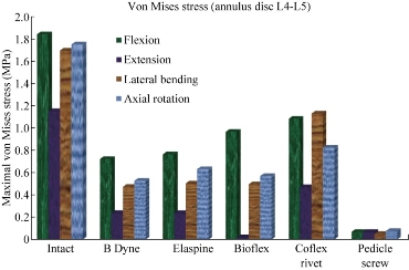
Fig. 24 Maximal von Mises stress at the annulus disc of L4-L5.
Fig. 25 Maximal von Mises stress at the INT disc model and total displacement of the L4-L5 spinal segment in flexion, extension, lateral bending and axial rotation for different devices of posterior RF and DF systems.
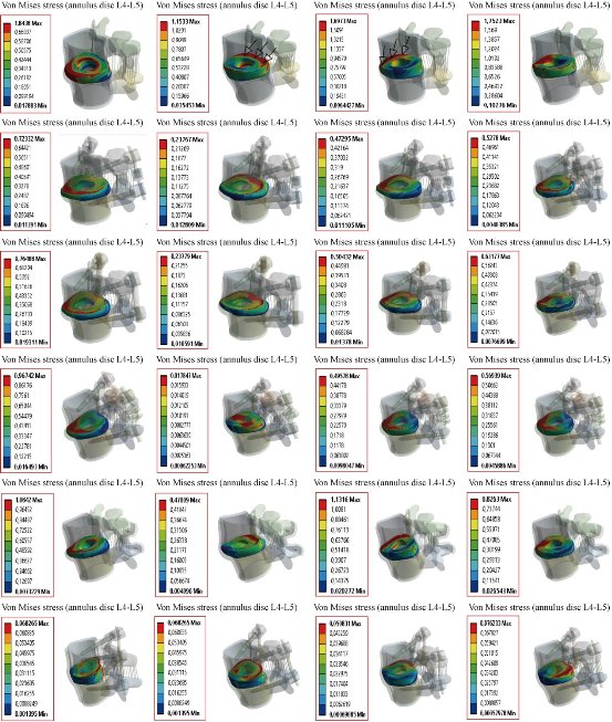
Fig. 26 Von Mises stress distribution at the annulus disc of the surgical segment L4–L5 in flexion, extension, lateral bending and axial rotation. The stress at the INT model and four models of B Dyne, Elaspine, Coflex rivet and pedicle screw fixation was concentrated at the posterior–superior regions of the annulus. For Bioflex model, the stress was concentrated in the left and right regions of the annulus, which were close to the superior and inferior sides of the endplate in the INT model. After implantation, the stress concentration of stress at the annulus disc diminished obviously.
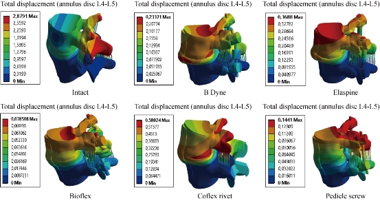
Fig. 27 Total displacement at the motion segment and von Mises stress distribution at the annulus disc of the surgical segment L4–L5 in extension for various surgical models.
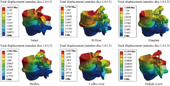
Fig. 28 Stress distribution of the annulus disc of surgical segment L4–L5 in flexion for various surgical models.
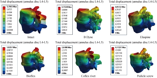
Fig. 29 Stress distribution of the annulus disc of the surgical segment L4–L5 in right lateral bending for various surgical models. The stress was concentrated at the right regions of the annulus, which were close to the superior and inferior sides of the endplate in the INT and defect models. Coflex rivet model have the most even annulus disc stress distribution. After pedicle screw fixation, the stress concentration of the annulus disc diminished obviously.
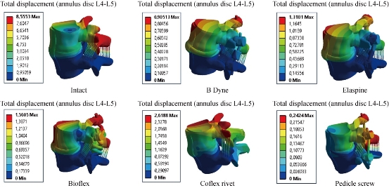
Fig. 30 Stress distribution of the annulus disc of surgical segment L4–L5 in right axial rotation for various surgical models.
Maximal von Mises stress at the posterior fixation system to the spinal segment L4-L5
Fig. 31 shows the maximal von Mises stress at the posterior fixation system to the spinal segment L4-L5 in flexion, extension, lateral bending and axial rotation. Bioflex, Coflex rivet and pedicle screw fixation models decreased von Mises stress at the posterior fixation system of the surgical segment L4–L5 in flexion, extension, lateral bending and axial rotation. However, B Dyne and Elaspine models increased von Mises stress at the posterior fixation system of the surgical segment L4–L5 in flexion, extension, lateral bending and axial rotation. Fig. 32 presents the contours for five models of fixation. Maximal von Mises stress revealed in the dynamic posterior fixation system of Elaspine model was 1365.2 MPa in flexion, 438.64 MPa in extension, 897.49 MPa in lateral bending and 1842.3 MPa in axial rotation. The highest maximal von Mises stress value for the posterior fixation system of Elaspine model also appeared in B Dyne model which was 1164.6 MPa in flexion, 418.1 MPa in extension, 887.76 MPa in lateral bending, and 787.64 MPa in axial rotation (Fig. 32). Fig. 32 shows the two EF models Bioflex and Coflex rivet with pedicle screws inserted in the two lumbar segments of L4- L5, The two instrumented models were subjected to a compression load P with bending moment P1 on a four physiological plane. The results showed that the maximal von Mises stress in the posterior fixation system equalled to 18.192, 0.4320, 10.164 and 11.471 MPa for Bioflex system and 142.24, 123.18, 207.32 and 134.72 MPa for Coflex rivet system (contour in red). On the other hand, Fig. 32 shows that the posterior RF system, pedicle screw fixation, absorbed von Mises stress which equalled to 18.192, 0.432, 10.164 and 11.471 MPa (contour in red) in flexion, extension, lateral bending and axial rotation. We concluded that the implantation of the pedicular screws could ensure the stability of all the movements and could reconstruct the posterior vertebral structure for the sharing of the loads in order to reduce the annular stress at the surgical segment. Fig. 32 shows the stress distribution of the posterior fixation system to the spinal segment L4-L5 in flexion, extension, lateral bending and axial rotation for various surgical models. The stress was concentrated at the right regions of the annulus, which were close to the superior and inferior sides of the endplate in the defect model. After implantation, the stress concentration of the annulus disc diminished obviously. The FEA on five models of fixation in order to stabilize L4-L5 motion segment was performed. RF and DF system models were evaluated. Maximal displacement for the motion segment was observed in Coflex rivet model. In flexion, Bioflex model between the two vertebrae permitted the complex to deflect up to 29.64 mm for the top anterior edge of the L4 vertebra. In flexion, pedicle screw fixation model revealed relatively less displacement for the motion segment by 2.47% reduction against Coflex rivet model. Noticeably higher fixation degree of the RF system was due to the straight rigid connector rod between pedicle screws. In such a firm structure, a considerable share of the loading energy was consumed to bend the rigid rod. In the RF of pedicle screw fixation model, the overall displacement of the motion segment was associated with the bending deflection of the straight rod. B Dyne, Elaspine and Bioflex models on the other hand experienced higher displacement in comparison with pedicle screw fixation model. It may be confusing how the two models, B Dyne and Elaspine,with an extra component of polymer-spacer i.e. silicone, received higher movement of displacement; however, it was noted that stainless steel rigid connector rod in pedicle screw fixation model was replaced by a silicone rod which possessed Young's modulus approximately half of the RF rod. Thus, the overall resistance of the fixation system against the external loading of flexion was remarkably diminished, and the maximal displacement in Coflex rivet became 36.81% greater than in pedicle screw fixation model. Fundamental diversities in these five models led to different behavior mechanics of the posterior fixation systems. In pedicle screw fixation model, the rigid rod resisted against the loading and the exerted energy was devoted to bending the rod. In flexion, the two rods of Elaspine model were strained, but the anterior half of the rod of silicone was compressed and constrained the rising of the movement of the motion segment. In Bioflex model, loading energy was consumed to compress or strain the spring ring, but the compression of the spring directly resulted in shortening of the ring's ends. in flexion, the overall displacement of the motion segment increased up to the maximal value of 1.59 mm. It should also be considered that characteristics of the spring provided in the connecting rod in Bioflex model was of crucial importance in the results. Diameter of the rod, diameter of the ring, number of the rings and density of the rings per length could influence the stiffness of such a design. After implantation, maximal stress at the IVD also occurred in Coflex rivet model. Provision of the extreme movement for the motion segment resulted in an increase of stress at the anterior regions of the L4-L5 IVD. The maximal stress with these fixation systems was 1.13 Mpa, less than those reported in other numerical works. For instance, in flexion the maximal stress reported for Bioflex model by Zhang et al was roughly 0.96 MPa. It was then concluded that the loading was in medium range of load exertion of the human back based on an in-vivo experiment reporting that healthy human in relax standing sustained 0.5 MPa in the IVD. In the present study, we also showed that the rivet connecting the metal wings and bony spinous process provided more security than the conventional device. Therefore, the rivet could improve load transmission on the posterior spinal structure to decrease the stress concentration on the annulus disc at the surgical segment in all motions. However, Coflex rivet constrained the surgical segment in all motions and increased displacement at the segment L4–L5, especially in flexion. Therefore, Coflex rivet increased annulus stress at both the segments of L4–L5 in flexion and extension. The numerical results showed that the tow posterior fixation system, both RF and DF, played a very important role in the absorption and minimization of stress in the lumbar segment L4-L5. On the other hand, the three fixation systems, Elaspine, Bioflex, Coflex rivet and pedicle screw fixation also played a great role in reducing the stress compared to INT model. In general, the posterior fixation system, both RF and DF, as well as those reinforced by the pedicle screw gave a lower level of stress at the cortical and spongy bones of the lumbar segment L4-L5, as compared to the INT model. Several assumptions were considered in the present numerical analysis. The most important one was to ignore the existence and the roles of the muscles acting on vertebral bodies which could also resist against the loading; however, since the goal was to compare the fixation systems, the analysis neglected them. Moreover, it should be taken into account that the loading of analysis was adopted from the experimental testing. Similar numerical simulations could elucidate the efficacy of such fixation systems in other cases as well.
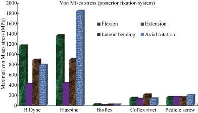
Fig. 31 Maximal von Mises stress at the posterior fixation system to the spinal segment L4-L5 in flexion, extension, lateral bending and axial rotation.
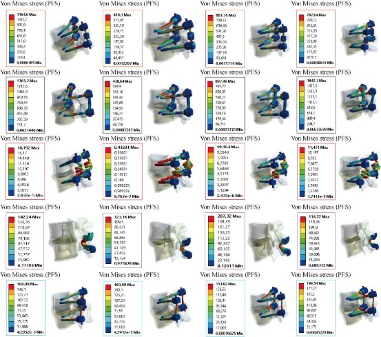
Fig. 32 Von Mises stress distribution of the posterior fixation system (PFS) to the spinal segment L4-L5 in flexion, extension, lateral bending and axial rotation for various surgical models.
Conclusions
FEM is a very precise technique used to analyze structural stresses. With its application in engineering, the method can solve many equations to calculate the stresses based on the mechanical properties of the structures being analyzed. FEM has many advantages highlighted by the possibility of including the heterogeneity and irregularity of the contour of the spine in the design of the model and the relative ease with which the loads can be applied to different directions and sizes for more complete analysis. Elaspine, Bioflex, Coflex rivet and pedicle screw fixation implantation can provide stability in all motions and can reconstruct the posterior spinal structure for load sharing to reduce annulus disc stress at the surgical segment L4-L5. However, Coflex rivet caused a higher displacement and stress at the disc. As a general conclusion, the application of fixation systems can considerably reduce the load on the IVD and prepare conditions for healing of the injured IVD. Moreover, the four fixation systems, Elaspine, Bioflex, Coflex rivet and pedicle screw fixation play too great a role in reducing the stress compared to INT model. In general, the posterior fixation systems, RF, DF or reinforced by pedicle screw give a lower level of stress at the cortical and spongy bone of the lumbar segment L4-L5, as compared to the INT model. Furthermore, dynamic modes of fixation, i.e. B Dyne, Elaspine, Bioflex and Coflex rivet, confer the possibility of movement to the motion segments in order to facilitate the spinal activities.
Acknowledgements
The authors kindly appreciate Mr. Said Kebdani and Smail Manssouri for their help in model preparation.
Authors’ contributions
All authors had equal role in design, work, statistical analysis and manuscript writing.
Funding and support
This paper was done by personal expenses.
Conflict of Interests
The authors declare that no competing interest exists.
References
Copyright© 2017 Said Kebdani, Samir Zahaf, Bensmaine Mansouri, and Benaoumeur Aour. This is an open-access article distributed under the terms of the Creative Commons Attribution License, which permits unrestricted use, distribution, and reproduction in any medium, provided the original author and source are credited.

|
Nano Biomedicine and Engineering. Copyright © Shanghai Jiao Tong University Press |
 |