Research Article
Biomechanical Evaluation of Two Posterior Lumbar Intervertebral Fusion Surgical Scenarios Reinforced by a Rigid Posterior Fixation System in the Vertebral Column Analyzed by the Finite Element Method
Samir Zahaf 1*, Said Kebdani 1, Mehdi Ghalem 1, Abdelkader Mestar 3, Noureddine Zina 2, Benaoumer Aour 2
1 Département de génie mécanique, université des sciences et de la technologie d’Oran Mohamed Boudiaf, USTO-MB, BP 1505, EL M’naouer, 31000 Oran Algérie.
2 Laboratoire de Biomécanique Appliquée et Biomatériaux (LABAB), Département de génie mécanique, Ecole Nationale Polytechnique d’Oran –MA, BP 1523 ElMnaour, Oran, Algérie.
3 Département technologie des matériaux, université des sciences et de la technologie d’Oran Mohamed Boudiaf, USTO-MB, BP 1505, EL M’naouer, 31000 Oran Algérie.
* Corresponding authors. E-mail: samir.zehaf@univ-usto.dz; zahafsamir1983@gmail.com
Received: May 1, 2018; Accepted: Jul. 19, 2018; Published: Aug. 30, 2018
Citation: Samir Zahaf, Said Kebdani, Mehdi Ghalem, Abdelkader Mestar, Noureddine Zina, and Benaoumer Aour, Biomechanical Evaluation of Two Posterior Lumbar Intervertebral Fusion Surgical Scenarios Reinforced by a Rigid Posterior Fixation System in the Vertebral Column Analyzed by the Finite Element Methods. Nano Biomed. Eng., 2018, 10(3): 258-278..
DOI: 10.5101/nbe.v10i3.p258-278.
Abstract
Lumbar interbody fusion is a common procedure for treating lower back pain related to degenerative disc diseases, the following two scenarios of posterior lumbar interbody fusion cage (PLIF) were usually used, i.e., Model (I) posterior lumbar intersomatic fusion cage bilateral approach filled with bone graft (1) and (2), (Model II) PLIF with cage made of PEEK or titanium (Ti) materiel filled with bone graft. But the benefits or adverse effects among the two surgical scenarios were still not fully understood. In this regard, we installed these discs between the two vertebrae L5 and S1 of the spine, to ensure spinal stability and avoid slipping, we have used a posterior attachment system (6 screws plus 2 rods) at the pedicular levels of the lumbar vertebra (S1-L5, L5-L4). Finite element analysis (FEA), as an efficient tool for the analysis of lumbar diseases, was used to establish a three-dimensional nonlinear TH1-pelvic FE model (Intact Model) with the ligaments of solid elements. Then it was modified to simulate the two scenarios of PLIF. Two anterior bending moments (P2 and P3) with a P1 compression loading were applied to the 3D model of the spine (TH1-pelvic), respectively. Different mechanical parameters were calculated to evaluate the differences among the three surgical models. The results of numerical values show that these disks played a very important role in the absorption of the stresses and to minimize, On the other hand, the lumbar inter-somatic cage (Model II) filled with cancellous bone is too great a role in reducing the stress compared to another synthetic (Model I) disc. In general, the new model of the inter-somatic cage filled with cancellous bone and reinforced by a posterior fixation system has given a lower level of stress in the cortical bone and the spongy bone of the lumbar vertebra (L5) compared to the healthy disk (D1). The findings provide theoretical basis for the choice of a suitable surgical scenario for different.
Keywords: Spinal fusion cage; Spine; Discs; Lumbar-Thoracic; Intervertebral discs; Finite element; Biomechanics; Von Mises stress-strain; Cage; PEEK; Ligaments; Grafton bone; Nonlinear
Abbreviations: ALL = anterior longitudinal ligament; PLL = posterior longitudinal ligament; TL = transverse ligament; LF = ligamentum flavum; ISL = interspinous ligament; SSL = supraspinous ligament; CL = capsular ligament; SL = Sacrotuberous Ligament; SPL = Sacroiliac posterior Ligament; IL = Interosseous Ligament); AIB = autogenous iliac bone (AIB); PEEK = polyetheretherketone; ASD = adjacent segment degeneration (ASD); PLIF = posterior lumbar interbody fusion; DIV = disc intervertebral.
Introduction
The lumbar interbody fusion procedure is an effective and popular surgical technique for treating low back pain related to degenerative disc disease [1]. This procedure restores disc height, enlarges the stenotic foramen, stabilizes the spine, and provides mechanical strength between vertebrae. However, it has been argued that various spinal fusions restrain motion at the surgical level. This local environmental change at the surgical level results in high stress at the adjacent disc levels and accelerates degeneration. Patients may need to undergo another surgery for extended fusion at the adjacent levels. Clinical studies have reported incidence rates ranging from 6% to 58% [2–5]. Therefore, a non-fusion artificial disc was developed to solve the adjacent segment problems. The aims of posterior lumbar interbody fusion (PLIF) procedure using cages or bone grafts are to provide stability of the motion segment and to facilitate the fusion process. After about 60 years of development and update, the surgical scenarios with cages or autogenous iliac bone (AIB) have been widely used. The PLIF with AIB provided high fusion rate because the AIB was histo-compatible and non-immunogenic [1, 2]. However, several studies reported the major complications of this surgical method with a wide range of incidence varying between 1% and 39%, such as collapse, retropulsion of the grafted bone, and pseudoarthrosis [3-6]. To resolve such problems, the PLIF with cages was designed in 1991 [7]. The advantage of this surgical scenario was that the cages separated the mechanical and biologic functions of the PLIF. Many studies reported that the PLIF with cages could provide satisfactory clinical results [8-10]. However, this surgical scenario produced new problems such as adjacent segment degeneration (ASD), fine motion and mote of cages, and implants damage [11, 12]. Recently, with the development of material industry, polyetheretherketone (PEEK) aroused wide concern. Previous studies showed that PEEK was non-resorbable and elicited minimal cellular response, intracutaneous, and intramuscular toxicity [13, 14]. Both the in vitro and finite element (FE) studies showed that the implants made of PEEK material provided good experimental and clinical performances [15-20]. The finite element method, as an essential complement for the in vitro biomechanical studies, has been widely used for the study of lumbar spine [9-12, 20-22]. However, the major deficiency of FE model of lumbar spine was the simplification of both the anatomic structures and material properties of ligaments. Although the influences of fusion rate, and ASD on the range of motion, stiffness, flexibility of lumbar spine following the PLIF procedure with AIB and PLIF with cages made of PEEK or Ti materiel have been investigated using FE method, respectively. To our knowledge, there are few studies evaluating the benefits or adverse effects among these three surgical scenarios using the model contained ligaments of three dimensional (3D) solid elements. The aim of this study was to comparatively investigate the differences among two types of fusion construct, which may provide the oretical basis for the choice of a suitable surgical scenario for different patients. On the other hand, I studied in this article a 3D model of the spine implanted by two models of the lumbar intersommatic cage innovative by specialists in the biomechanical field (Zhitao Xiao, Wang Liya, He Gong and Dong Zhu in 2012), some of the biomechanics researchers and we have installed these discs between the two vertebrae L5 and S1 of the spine, to ensure spinal stability and avoid slipping, we installed a posterior attachment system (6 screws plus 2 rods) at the pedicular levels of the lumbar vertebra (S1-L5, L5-L4). For the boundary condition, The overall mass (Head, Neck, Arm (left + right), Forearm (left + right), hand (left + right)) is 13.4517kg to divided by the top surface of the thoracic vertebrae TH1 representing the pressure P1, P2 load represents the mass of the body superior Trunk is 12.768kg, the distance between the point of application of the load and axis (yy ') is 200 mm. The total mass of the lower trunk of the human body is equal to 22 kg; represented by P3, the distance between the point of application of the load and the axis (yy ') is 250 mm. For the boundary conditions we fixed the basin (Embedding the basin). It is for this technique that we have used finite elements in three dimensions and using the software ANSYS to know the extent of the realization of these cages under the influence of the load applied to them.
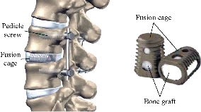
Fig. 1 posterior lumbar interbody fusion (PLIF)
Experimental
In the present study three FE models of spine are constructed : The first model is of an intact lumbar-thoracic spine; The second model consists of two bilateral inter-somatic lumbar cages (PEEK) filled by the graft bone implanted between the two segments (S1-L5), The third model consists of a single lumbar inter-somatic cage (PEEK) filled by the graft bone implanted between the two segments (S1-L5), The two models are shown in Fig. 5 and Fig. 9, The two implanted models are reinforced by two rods fixed by sex screws (pediculars) at the level of the lumbar vertebrae (S1-L5, L5-L4).
FE model of the intact spine (INT Model)
A 3D nonlinear FE model of TH1-S1 segment that consisted of five lumbar vertebral bodies, twelves thoracic vertebral bodies, one sacral vertebra, one pelvis, seventeen annulus fibrosus, seventeen nucleus pulposus, and one hundred and twenty-seven spinal ligaments was developed using MIMICS and Solidworks2016 software. Geometrical details of all the parts in the model were obtained from computed tomography (CT) images with a slice distance of 2.5 mm (512 × 512 resolution, 8-bit, and a pixel size of 0.91 mm) of a 23-year old male volunteer. CT data were imported into MIMICS software to establish seventeen vertebral bodies, one pelvis, seventeen annulus fibrosus (ANN) and seventeen nucleus pulposus (NUC), which was shown in Fig. 2. The material properties of the INT model are listed in Table 1 and were chosen from previous studies [23–41]. A ten-node solid element type (Solid187) was used for modeling the cortical bone, cancellous bone, endplate, and annulus fibrosus. Cortical bone and cancellous bone were assumed to be homogeneous and isotropic [23-28]. The intervertebral disc consisted of annulus ground substance and nucleus pulposus, which embeds collagen fibers in the ground substance. The non-linear annulus ground substance was simulated by using an isotropic and simulated by ten-node solid element, type (Solid187) [24-30], All ten ligaments (Anterior Longitudinal Ligament, Posterior Longitudinal Ligament, Ligamentum Flavum, Intertransverse Ligament, Inter-Spinous Ligament, Supra-Spinous Ligament, Capsular Ligament, Sacrotuberous Ligament, Sacroiliac posterior Ligament, Interosseous Ligament) are simulated by tetrahedral elements, type (Solid187) conforming to defined parametric surfaces interfaces and they were arranged in the anatomical direction given by the text book [30]; the cross-sectional area of each ligament was obtained from previous studies [36-41]. The selection of constitutive equations of the vertebral bone is defined as the part of the bone which carries the inter vertebral disc, composed of cortical bone, cancellous bone, the posterior arch, with a Young's modulus of about 12000 MPa. It is well known that cortical bone has better load capacity than the cancellous bone. The magnitudes of 100 MPa (cancellous respectively) were observed in all studies by various researchers. Since physiologically the nucleus is fluid filled, the elements were assigned low stiffness values (1 MPa) and near incompressibility properties (Poisson’s ratio of 0.499). Biologically, the annulus fibrosus is comprised of layers of collagen fibers, which attributes to its non-homogenous characteristics. However, due to limitations in modeling abilities, in this study the annulus fibrosus was defined as a homogenous structure with a magnitude of 4.2 MPa.

Fig. 2 Spine studied. (a) Lateral (left) view; (b) Dorsal view; (c) Front view; (d) Lateral (right) view.
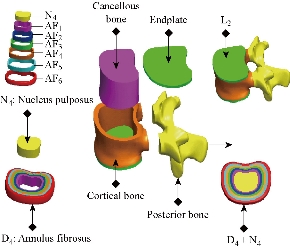
Fig. 3 3D modeling thoracic vertebra L3, D4 disc of the lumbar spine (SOLIDWORKS 2016).
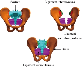
Fig. 4 Model details of basin and sacrum (ligaments).
FE model of the PLIF Model (I)
To simulate the PLIF model (I), the S1-L5 level of the INT model underwent laminectomy and partial discectomy, which included removal of supraspinous, interspinous, and flavum ligaments; then, bilateral PEEK alloy cages (10mm×14mm×25 mm) with pedicle screw fixation were inserted in this model (Fig. 7), six pedicle screws (r = 3 mm) and two rods (r = 2.5 mm) are simulated by tetrahedral elements, type (Solid187). The beam element was designed as a full constraint between the pedicle screws and vertebrae. Two PEEK cages are placed between the vertebral bodies (S1-L5), and the bone–cage interface was modeled through surface-to-surface contact elements that were able to transmit compression forces, but not tension. The small teeth on the cage were neglected in our simulation; however, The PLIF model consists of 148,178 elements and 174,617 nodes (Fig. 16).
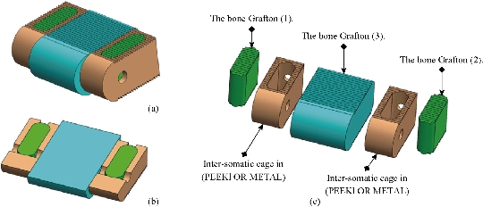
Fig. 5 Lumbar intersomatic fusion cage bilateral approach [42-45]. (a) Isometric perspective assembly; (b) Sectional assembly; (c) Exploded view.
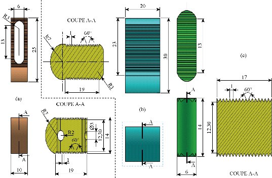
Fig. 6 Definition drawing of the lumbar intersomatic fusion cage bilateral approach [42-45]. (a) Intersomatic cage made of PEEK; (b) Bone graft (2); (c) Bone graft (1).
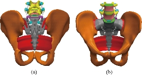
Fig. 7 positioning of the screws and the lumbar intersomatic fusion cage bilateral. (a) Posterior view; (b) Anterior view.

Fig. 8 Replacement of lumbar intersomatic fusion cage bilateral approach [42-45].
FE model of the PLIF Model (II)
To simulate the PLIF model (II), the S1-L5 level of the INT model underwent laminectomy and partial discectomy, which included removal of supraspinous, interspinous, and flavum ligaments; then, PEEK alloy cage with pedicle screw fixation were inserted (Fig. 11). In this model, six pedicle screws (r = 3 mm) and two rods (r = 2.5 mm) were modeled by tetrahedral elements, type (Solid187). The beam element was designed as a full constraint between the pedicle screws and vertebrae. One PEEK cage was placed between the vertebral bodies (S1-L5), and the bone cage interface was modeled through surface-to-surface contact elements that were able to transmit compression forces, but not tension. The small teeth on the cage were neglected in our simulation; however, The PLIF model consists of 386,641elements and 444,788 nods) (Fig. 17).

Fig. 9 Lumbar intersomatic fusion cage [42-44, 46]. (a) Sectional exploded view; (b) Isometric perspective assembly; (c) Sectional assembly.
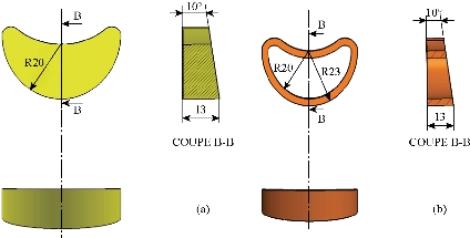
Fig. 10 Definition drawing of the lumbar intersomatic fusion cage [42-44, 46]. (a) Graft bone; (b) Intersomatic cage made of PEEK.
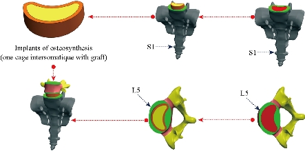
Fig. 11 Replacement of lumbar intersomatic fusion cage bilateral approach [42-44, 46].
FE model of bilateral pedicle screw fixation implanted into the S1-L5 segment (Pedicle screw fixation Model (III))
This model was a defect model implanted with pedicle screw fixation at the segment (S1-L5, L5-L4). The difference between the pedicle screw fixation model and the abovementioned implantation models was that the pedicle screw fixation model preserved the supraspinous ligaments and interspinous ligaments (Fig. 12). The pedicle screw fixation consisted of two rods (diameter, 5 mm) and six pedicle screws (diameter, 6 mm). The pedicle screws were inserted through the pedicles of the S1 and L5 vertebrae bilaterally. The pedicle screws were simplified as cylinders. The screw-bone interfaces were assigned to be fully constrained. The material used for the pedicle screws was Ti-6Al-4V. Young’s modulus and Poisson’s ratio were assigned to be 110 GPa and 0.3, respectively for the PLIF Model (I) (Table 2). The material used for the pedicle screws was Ti-6Al-4V. Young’s modulus and Poisson’s ratio were assigned to be 104 GPa and 0.3, respectively for the PLIF Model (II) (Table 2). Each of the component parts of the final geometric model is meshed independently. An automatic meshing process is used in vertebrae, and a manual meshing is applied to intervertebral discs (nucleus pulposus, annulus fibrous and fibers embedded in it) and the various ligaments. The complete model (Fig. 15) consists of 117,8694 elements and 200,5025 nodes (528,651 degrees of freedom). The cortical bone have been modeled with tetrahedral elements (644,583 elements) and the cancellous bone have been modeled with tetrahedral elements (244,460 elements), All the different ligaments (ALL, PLL, FL, TL, ISL, SSL, CL, STL, SPL, IL) were modeled with tetrahedral elements (24469, 6607, 13446, 131648, 13158, 8279, 27072, 10128, 3280, 8306 elements) and the posterior bone was modeled with tetrahedral elements (132,464 elements), the nucleus pulposus in the fibrous annulus have been modeled with tetrahedral elements (114,036 elements), and the six annulus fibrosus (AF) were modeled with tetrahedral elements (244,800 elements) correspond to wedge type elements for geometric adaptation in different areas of the model, the cartilage endplates have been modeled with tetrahedral elements (87,710 elements). All elements are of linear approximation. The final number of elements in the whole model was obtained after a sensitivity analysis. To this respect a mesh refinement was performed in order to achieve a convergence towards a minimum of the potential energy, both for the whole model and for each of its components, with a tolerance of 1% between consecutive meshes. Fig. 15 shows a detail of the finite element model of S1-TH1 vertebral disc. In order to simulate the connection between the different elements of the model, several groups of boundary conditions were considered: contact conditions between apophyses, join conditions in the various insertions of ligaments, and join conditions between vertebrae and intervertebral discs. Immobilization of the base of the basin is imposed as a support condition (Fig. 18). The meshing of the components is simple and consists of 10-node tetrahedral linear elements (Fig. 16 and 17). Since the posterior attachment system with the lumbar inter-somatic cage experiences the greatest stresses and strains under eccentric loading, it is necessary to mesh this component into small elements (Fig. 16 and 17) in order to ensure optimum accuracy in the calculations. Fig. 16 shows that the bilateral lumbar intersomatic cage (Model I) consists (34,142 elements, 54,500 nodes) and the three grafton bones (114,036 elements, 120,117 nods). Fig. 17 shows that the meshing of the cage intersomatic lumbar (Model II) consists (33,191 elements, 51,273 nods) and the grafton bone (55740 elements, 79,699 nods).
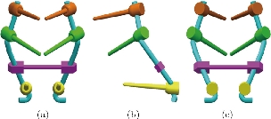
Fig. 12 Posterior lumbar fixation system [43]. (a) Front view; (b) Left view; (c) Dorsal view.

Fig. 13 Definition drawing of the posterior lumbar fixation system [43]. (a) Pedicle screw; (b) Rod; (c) Belt.
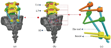
Fig. 14 Replacement of the lumbar fixation system [43]. (a) Total assembly (6 screws with 2 rods); (b) Positioning pedicular screws; (c) Posterior attachment system.
Table 1. Material properties used in the FE model
|
Material |
Young modulus E (MPa) |
Poisson coefficient |
References |
|
Cortical bone |
12000 |
0.3 |
[23-28] |
|
Cancellous bone |
100 |
0.2 |
[23-28] |
|
Posterior bone |
3500 |
0.25 |
[23-28] |
|
Cartilage endplates |
12000 |
0.3 |
[24-30] |
|
Annulus fibrosus |
4.2 |
0.45 |
[24-30] |
|
Nucleus pulposus |
1 |
0.499 |
[24-30] |
|
Anterior longitudinal ligament |
20 |
0.3 |
[36-41] |
|
Posterior longitudinal ligament |
20 |
0.3 |
[36-41] |
|
Ligamentum flavum |
19.50 |
0.3 |
[36-41] |
|
Intertransverse ligament |
58.7 |
0.3 |
[36-41] |
|
Inter-Spinous ligament |
11.6 |
0.3 |
[35-40] |
|
Supra-Spinous ligament |
15 |
0.3 |
[35-40] |
|
Capsular ligament |
32.9 |
0.3 |
[35-40] |
|
The basin |
12000 |
0.3 |
[41] |
|
Sacrotuberous ligament |
40 |
0.3 |
[41] |
|
Sacroiliac posterior ligament |
40 |
0.3 |
[41] |
|
Interosseouse ligament |
40 |
0.3 |
[41] |
Table 2 Summary of the components and their mechanical behaviour for the two posterior fusion systems
|
Type of prosthesis |
Component (materials) |
Young modulus E (MPa) |
Poisson coefficient |
References |
|
Two lumbar intersomatic cages bilateral approach with bone Grafton [45]. |
Bone grafton |
100 |
0.2 |
[42] |
|
Two lumbar intersomatic cages bilateral approach (PEEK) |
3500 |
0.3 |
[44] |
|
|
(6 pedicular screws plus 2 rods, belt) titanium |
110000 |
0.3 |
[43] |
|
|
One lumbar intersomatic cage with bone Grafton [46]. |
One Lumbar Intersomatic Cage (PEEK) |
3500 |
0.3 |
[44] |
|
Bone Grafton |
100 |
0.2 |
[42] |
|
|
(6 Pedicular screws plus 2 rods, belt) titanium |
104000 |
0.3 |
[43] |

Fig. 15 Spine 3D finite element modeling (ANSYS 16.2).

Fig. 16 Finite element model of the lumbar intersomatic fusion cage bilateral approach with bone graft [40].

Fig. 17 Finite element model of the lumbar intersomatic fusion cage with bone graft [41].
Boundary and loading conditions
The diagram (Fig. 18) represents a 3D model of the vertebral column of a normal person implanted by one or two cages in the DIV (D1) and then placing rods fixed by six screws (pedicular) at the level of the pedicles. The overall mass (Head, Neck, Arm (left + right), Forearm (left + right), hand (left + right)) is 13,4517kg to divided by the top surface of the thoracic vertebrae Th1 representing the pressure P1, P2 load represents the mass of the body superior Trunk is 12,768kg, the distance between the point of application of the load and axis (yy ') is 200 mm. The total mass of the lower trunk of the human body is equal to 22 kg; represented by P3, the distance between the point of application of the load and the axis (yy ') is 250 mm. For the boundary conditions we fixed the sacrum (Embedding the sacrum) (Fig. 18). We propose in this section to draw up a comprehensive study of the distributions of stresses and elastic strain in the intervertebral discs, the cortical bone, cancellous bone, the posterior arch, anterior longitudinal ligament and posterior according to the supported loads Distributions of global stress state for each component of our model were presented. A quantitative analysis was performed based on a scale of progressive visual colors predefined by the software used (ANSYS Workbench 16.5), ranging from dark blue to red.
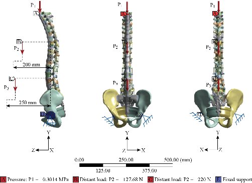
Fig. 18 Model biomechanics of the spine (anterior loading).
Results and Discussion
Biomechanical analysis of three FE models
Stress and strain of Von Mises in the DIV (Intact Model, Model I, Model II)
Fig. 19 shows clearly that the anterior load affects the disk D1, D15 and D16 is the three most sought discs compared to other drives in the thoracic lumbar spine. A load applied to the upper surface of the TH1 thoracic vertebra of the spinal column causes a high concentration of maximum Von Mises stresses in the anterior portion of the two components of the disc D1 (N1, D1) (red section) this is mentioned in Fig. 20. Moreover, the Von Mises stresses and strains are minimal in the following intervertebral discs (D2, D3, D4, D5, D6, D7, D8, D9, D10, D11, D12, D13, and D14), see Fig. 19. Fig. 19 shows the Von Mises strain histogram in the inter vertebral discs for a normal person load 13.25 kg. We note that the Von Mises strains values are highest in the three discs D1, D15 and D16 outline in red; this is mentioned in Fig. 20. Fig. 20 shows that the anterior loading of a normal person presents a maximum stresses and strains of Von Mises concentrated in the intervertebral disc D1, that is to say between the sacrum and the lumbar vertebrate L5, On the other hand, Fig. 20 clearly shows that the anterior loading with a lever arm equal to 250 mm presents maximum Von Mises stresses and strains concentrated in the disk D1 and are equal to (13.485 MPa, 3.3539). We notice in the Fig. 21 that the mixed loading (compression P1 + bending moment (P3)) present a contour of the maximum stresses part red in the disk D1 and we see in this figure the front part of the disk D1 compressed and The other part tension. We note in Fig. 21 that the disc degeneration often begins after an asymptomatic phase dehydration through cracks, tears in the annulus fibrosis of the disc D1. The nucleus N1 can then, along these cracks, migrate into the thickness of the ring D1 and cause pain of the lumbar, acute or chronic. If it moves even more through the ring, the core N1 can protrude at the posterior face of the disc D1, forming a DISCAL HERNIA. This hernia can, through a complete rupture of the annulus, migrate into the vertebral canal laterally, or upwards, or downwards, and even excludes when exiting the disc. This disc herniation can compress, "pinch", one or more nerve roots near the disc. It is the cause of symptoms: "sciatica" when the pain sits behind the thigh, or "cruralgia" when the pain sits in front of the thigh. It comprises variably pain in the lower limbs, tingling sensations or tingling (paresthesia), sensations of perturbation of sensitivity (dysesthesia), up to anesthesia, which may include anesthesia, motor disorders (loss of muscular strength or partial or complete paralysis of part of the lower limb), as shown in Fig. 21. Fig. 22 shows a histogram of the maximum stresses and strains equivalent in the intervertebral discs. we notice that the spine undergoes a maximum concentration of stresses in the lumbar region, on the other hand the stresses equivalent in the two intervertebral discs at the segment (S1-L5) are equal respectively to (94.697 MPa, 13.485 MPa), as mentioned in Fig. 23. A loading applied to the upper surface of the thoracic vertebra TH1 of the spine causes a high concentration of the maximum strains of Von Mises in the anterior part of the intact disk D1 (red part) (Fig. 23). On the other hand, Fig. 23 shows that the two discs inserted between the two segments (S1-L5) absorbed maximum strains of Von Mises equal to (0.0524, 3.3539) with respect to the other discs of the spine. Fig. 24 shows the distribution of maximal stresses and strains in the components of the lumbar inter-somatic fusion cage bilateral approach that are equal to (94.697 MPa, 2.6469 MPa, 4.1597 MPa) (0.0297, 0.0524, 0.0491) contour in red, Since the replacement of the second lumbar interbody cage plays a very important role in reducing stress and aim to provide spinal stability (Fig. 24). Fig. 25 shows a histogram of the maximum stresses and strains equivalent in the intervertebral discs. we notice that the spine undergoes a maximum concentration of stresses in the lumbar region, on other hand, the stresses equivalent in the two intervertebral discs (Natural, Artificial) at the segment (S1-L5) are equal respectively to (22.354 MPa, 13.485 MPa), as mentioned in Fig. 26. A loading applied to the upper surface of the thoracic vertebra TH1 of the spine causes a high concentration of the maximum strains of Von Mises in the anterior part of the intact disk D1 (red part) (Fig. 26). On the other hand, Fig. 26 shows that the two disks inserted between the two segments (S1-L5) absorb maximum strains of Von Mises equal to (0.0064, 3.3539) with respect to the other discs of the spine. Fig. 27 illustrates the distribution of maximal stresses and strains in the components of the lumbar inter-somatic fusion cage (Model II) that are equal to (0.5136 MPa, 22.354 MPa) (0.0051, 0.0064) contour in red, Since the replacement of the second lumbar interbody cage plays a very important role in reducing stress and aim to provide spinal stability (Fig. 27). We see in Fig. 24 the replacement of artificial disc (Model I) shows that the distribution of maximal stresses and strains in the components of the lumbar inter-somatic fusion cage bilateral approach that are equal to (94.697 MPa, 2.6469 MPa, 4.1597 MPa) (0.0297, 0.0524, 0.0491) contour in red. On the other hand, Fig. 27 illustrates the distribution of maximal stresses and strains in the components of the lumbar inter-somatic fusion cage (Model II) that are equal to (0.5136 MPa, 22.354 MPa) (0.0051, 0.0064) contour in red, Since the replacement of the second lumbar inter body cage plays a very important role in reducing stress. in other words, Fig. 27 clearly shows that the anterior loading with a lever arm equal to 250 mm presents maximum Von Mises stresses and strains concentrated in the disc intact D1 and are equal to (13.485 MPa, 3.3539). We notice in Fig. 27 that the mixed loading (compression P1 + bending moment (P3)) present a contour of the maximum stresses part red in the disc D1 and we see in this figure the front part of the disc D1 compressed and the other part tension. In particular, the lumbar inter-somatic cage filled with spongy bone is too great a role in the reduction of the stress compared to another spinal fusion cage (Model II).
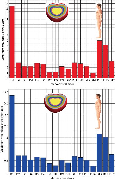
Fig. 19 Histogram of stresses and strains in the DIV for a normal person.
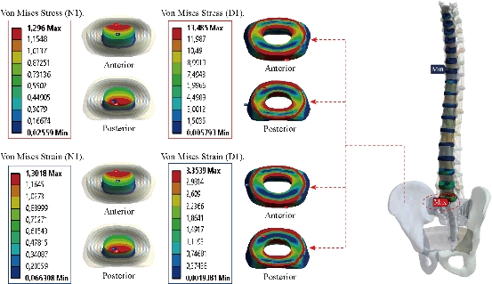
Fig. 20 Distribution of stresses and strains in the DIV D1 for normal person.
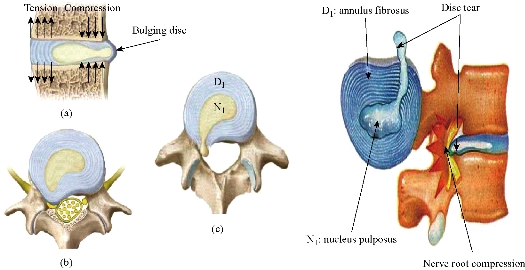
Fig. 21 Disc herniation: (a) Disc protrusion; (b) Nerve root compression; (c) Extrusion.
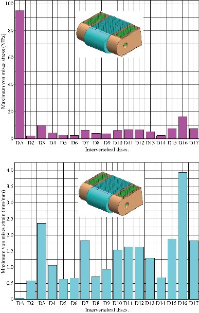
Fig. 22 Histogram of stresses and strains in the DIV (Model I).
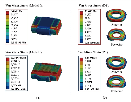
Fig. 23 Distributions of stresses and strains of Von Mises in the DIV of spine. (a) Spinal fusion cage (Model I); (b) Natural disc.
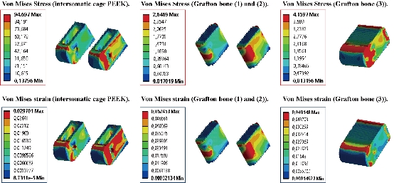
Fig. 24 Distribution of maximum stresses and strains of Von Mises in the lumbar intersomatic fusion cage bilateral approach (Model I).

Fig. 25 Histogram of stresses and strains in the DIV (Model II).
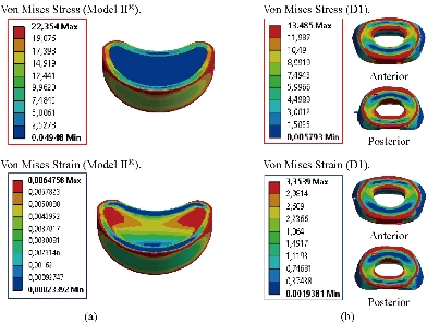
Fig. 26 Distributions of stresses and strains of Von Mises in the DIV of spine. (a) Spinal fusion cage (Model II); (b) Natural disc.
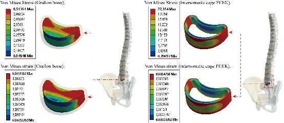
Fig. 27 Distribution of maximum stresses and strains of Von Mises in the lumbar intersomatic fusion cage (Model II).
Contour of maximum stresses and strains of Von Mises in the model of bilateral pedicle screw fixation implanted into the S1–L5 segment (Pedicle screw fixation Model (III))
Fig. 28 shows that the two EF model with pedicle screws inserted in the two segments (S1-L5, L3-L4). The two instrumented models were subjected to a compression load P1 with two bending moments P2, P3 on a single physiological plane. The results show that the maximum Von Mises stresses and strains in the posterior fixation system are equal to (1020.1 MPa, 1665 MPa, 0.0198, 0.01659) contour in red, we conclude that the implantation of the pedicular screws can ensure the stability of all the movements and can reconstruct the posterior vertebral structure for the sharing of the loads in order to reduce the annular stress of the surgical segment.
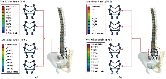
Fig. 28 Distribution of maximum stresses and strains in the posterior fixation system. (a) Spinal fusion cage (Model I); (b) Spinal fusion cage (Model II).
Contour of maximum stresses and strains of Von Mises in the cortical and spongy bone
A load applied to the upper surface of the thoracic vertebra TH1 of the spine results in a high concentration of maximum stresses and normal strains in the anterior and posterior part of the cortical bone (L5) (part in red) as shown in Fig. 29. On the other hand, Fig. 29 shows that the maximum of Von Mises stresses and strains in the cortical bone (L5) are equal to (163.38 MPa, 54.575 MPa, 35.129 MPa) (0.0137, 0.0045, 0.0030) respectively to the other components of the spine system. Fig. 30 shows that the implantation of the lumbar intersomatic cages with the six pedicle screw system inserted between the sacrum and the vertebra (L5) and simulated by the finite element method confirms a reduction of the equivalent stresses in the cancellous bone (L5) and decreased strains in said vertebra. We note in Fig. 30, the stresses and strains of Von Mises in the cancellous bone (L5) is decreased to (1.1891 MPa, 0.6034 MPa) (0.0122, 0.0062) this justifies that the two intersomatic lumbar models reinforced by a rigid posterior fixation system plays a very important role in stabilizing the movement of the spine.
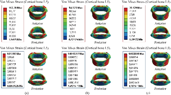
Fig. 29 Distribution of maximum stresses and strains in the cortical bone (L5). (a) Model Intact; (b) Spinal fusion cage (Model I); (c) Spinal fusion cage (Model II).

Fig. 30 Distribution of maximum stresses and strains in the cancellous bone (L5). (a) Model Intact; (b) Spinal fusion cage (Model I); (c) Spinal fusion cage (Model II).
Contour of maximum stresses and strains of Von Mises in the basin and sacrum
Fig. 31 shows the distribution of maximum Von Mises stresses and strains in the basin and sacrum of different modles.
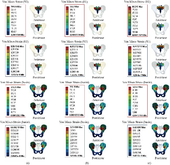
Fig. 31 Distribution of maximum stresses and strains in the basin and sacrum. (a) Disc Intact; (b) Spinal fusion cage (Model I); (c) Spinal fusion cage (Model II).
Comparison of three cases
Finite element analysis (FEA) is a sophisticated simulation method, and also an effective tool for elucidating biomechanics in the spine. In the biomechanical evaluations based on FEA, it is important to establish a model that can accurately reproduce the mechanical property of each part. Establishing such a model requires accurate data on anatomic structures and material properties [13]. However, since ligaments show complicated material properties and large deformation, it is difficult to establish an accurate model of ligaments in FEA. Many researchers used two-dimensional tension-only truss or cable elements to describe the function of ligaments [11, 13, 22, 26, and 29]. In the present study, the surrounding ligaments (anterior longitudinal ligament, posterior longitudinal ligament, ligamentum flavum, inter-transverse ligament, interspinous ligament, supraspinous ligament, capsular ligament, sacrotuberous ligament, posterior sacroiliac ligament and interosseous ligament) were modeled with three-dimensional solid and 10-node tetrahedral elements, type (Solid187) conforming to defined parametric surface interfaces. The material properties of ligaments were simulated by linear-elastic based on the experimental data. The validated results indicated that the model established in this study could effectively reproduce the mechanical behaviors of TH1-S1 thorcic-lumbar segment. In addition, another advantage of the model established in this study was that it could directly obtain the stresses and strains of the spinal fusion cage (Model I, Model II). The intensive discussions among the two surgical scenarios were shown below.
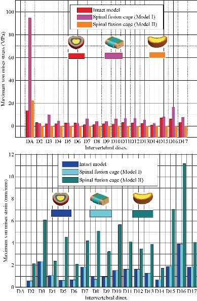
Fig. 32 Histogram of stresses and strains of Von Mises in the two lumbar intersomatic cages.
Stresses of the adjacent intervertebral discs
Both the postoperative following-up and biomechanical studies showed that the PLIF accelerated degeneration of adjacent segment and segmental instability [11]. The FE results showed that great changes were found in the stresses on the discs proximally adjacent to the fusion segment. These great changes in discs could be used to interpret the clinical findings of early degeneration of adjacent disc [12]. Implantation of the interbody lumbar cage (Model I) between the two segments (TH1-S1) shows an increase of the maximum stresses and deformations of Von Mises on the adjacent intervertebral discs (D2, D3, D4, D5, D6, D7, D8, D9, D10, D11, D12, D12, D13, D14, D15, D16, D17) during the applied loading, see Fig. 32. On the other hand, the implantation of the lumbar fusion cage (Model II) between the sacrum and the lumbar vertebra L5 gives minimal stresses and deformations of Von Mises on the intervertebral discs (D2, D3, D4, D5, D6, D7, D8, D9, D10, D11, D12, D12, D13, D14, D15, D16, D17) by providing the surgical model (Model I). This result showed that the surgical method using (Model II) could decrease the risk of degeneration of adjacent fusion discs. The ultimate purpose of the PLIF was to complete bone graft fusion, restoring the height of intervertebral space and finally achieving long-term stability of the lumbar spine. Therefore, the fusion rate of the bone grafts was the key point of the surgery, and it was also the issue that our study focused on. According to Wolff’s Law, bone can change its structure according to its mechanical environment. So the stresses on grafts may be used to predict the long-term fusion rate [20]. The contours of Von Mises stress and strain on the bone grafts Model I have been shown in Fig. 25. We can see that the stresses and deformations of Von Mises for the bone grafts (1), (2) and (3) are mainly concentrated on the anterior and posterior surface of the grafts, whereas the stresses do not traversed the central part of the graft (Fig. 25). On the other hand, in Model I the two fusion cages lumbar intersommatique bilateral approach absorbed maximum Von Mises stresses which are equal to 94.697 MPa contribution by the other components of the lumbar fusion cage Model II (Fig. 25). Fig. 27 shows that the stresses and strains of Von Mises for the bone grafts (1), (2) and (3) are mainly concentrated on the anterior and posterior surface of the grafts, whereas the stresses do not traversed the central part of the graft (Fig. 25). Implantation of the lumbar interbody somatic Model II between the lumbar vertebra L5 and the sacrum indicated a contours of the maximum stresses and deformations of Von Mises on the two components (graft bone, PEEK cage) were represented on Fig. 27. It can be seen that the stress of Model II focus mainly on the lower or upper surface of the graft bone, whereas the stresses do not cross the central part of the graft. On the other hand, the stress distribution in both models I and II was more extensive (Fig. 24 and 27), which can facilitate the fusion of the grafts to the end plate and improve the efficiency of the fusion of bone grafts. We note in Fig. 32 the Von Mises stresses reached a maximum value concentrated in the intervertebral disc (D1). We notice that the spine undergoes a maximum concentration of stresses in the lumbar region, on other hand the stresses in the two spinal fusion cages (Model I, Model II) at the segment (S1-L5) are equal respectively to (94.697 MPa, 22.354 MPa) as mentioned in Fig. 23 and 26. On the other hand, Fig. 32 shows that the two spinal fusion cages inserted between the two segments (S1-L5) absorbed maximum strains of Von Mises equal to (0.0524, 0.0064) with respect to the other discs of the spine. A compression load P1 plus two bending moments (P2, P3) shows the maximum stresses and strains equivalent in the intervertebral disc (D1). We see that the spine undergoes a maximum concentration of stresses in the lumbar region, on the other hand the equivalent stresses in the disc intact (D1) at the segment (S1-L5) are equal respectively to (13.485 MPa), as mentioned in Fig. 26. In particular, the lumbar inter-somatic cage filled with spongy bone is too great a role in the reduction of the stress compared to another synthetic disc (model intact). In general, the new model of the lumbar inter-somatic cage filled with spongy bone and reinforced by a posterior attachment system. It has given the lowest level of stresses at the level of the vertebra (L5) compared by natural disc and aim to provide spinal stability.
Conclusions
The finite element method (FEM) is a very precise technique used to analyze structural stresses. With its application in engineering, this method can solve many equations to calculate the stresses based on the mechanical properties of the structures being analyzed [49, 50]. FEM has many advantages highlighted by the possibility of including the heterogeneity and irregularity of the contour of the spine in the design of the model and the relative ease with which the loads can be applied to different directions and sizes for one analysis more complete. As a general conclusion, On the basis of the results of the analysis by this numerical method, the numerical results show that artificial disks (Model I, Model II) have played a very important role in the absorption of stresses and to minimize, On the other hand, the lumbar inter-somatic cage filled with spongy bone is too great a role in reducing the stress compared to another synthetic disc. In general, the new model of the inter-somatic cage filled with spongy bone and reinforced by a posterior fixation system has given a lower level of stress in the cortical and spongy bone of the lumbar vertebra (L5) Compared to the healthy disk. The model can also be used as the basis for our further study, in which surgical models having cages with different shapes and grafts will be developed. Besides, bone remodeling theory will be introduced to predict the long-term bone graft fusion, which could provide theoretical basis for clinical postoperative rehabilitation.
Acknowledgements
The authors extend their appreciation to the Director of Scientific Research at LABPS for funding the work through the Biomechanics Research Group.
Authors’ contributions
All authors had equal role in design, work, statistical analysis and manuscript writing.
Funding/Support
This paper had been done by personal expenses.
References
1.E.D. Arrington, W.J. Smith, H.G. Chambers, et al., Complications of iliac crest bone graft harvesting. Clinorthop Relat R, 1996, 329: 300-309.
2.T. Asazuma, K. Masuoka, T. Motosuneya, et al., Posterior lumbar interbody fusionusing dense hydroxyapatite blocks and autogenous iliac bone. Clinical and radiographic examinations. J Spinal Disord Tech, 2005, 18: S41-S47.
3.D.K. Sengupta, E. Truumees, C.K. Patel, et al., Outcome of local bone versus autogenous iliac crest bone graft in the instrumented posterolateral fusion of the lumbar spine. Spine, 2006, 31(9): 985-991.
4.Y. Arai, M. Takahashi, H. Kurosawa H, et al: Comparative study of iliac bone graft and carbon cage with local bone graft in posterior lumbar interbody fusion. J Orthop Surg, 2002, 10: 1-7.
5.C.G. Hutter, Posterior intervertebral body fusion-a 25 year study. Clin Orthop, 1983, 179: 86-96.
6.J.W. Brantigan, Pseudoarthrosis rate after allograft posterior lumbar interbody fusion with pedicle screw and plate fixation. Spine, 1994, 19: 1271-1280.
7.J.W. Brantigan, A.D. Steffee, J.M. Geiger, A carbon fiber implant to aid interbody lumbar fusion. Mechanical testing. Spine, 1991, 16(6): 277-282.
8.S.D. Kuslich, G. Danielson, J.D. Dowdle, et al., Four-year follow-up results of lumbar spine arthrodesis using the bagby and kuslich lumbar fusion cage. Spine, 2000, 25(20): 2656-2662.
9.H.J. Kim, H.J. Chun, S.H. Moon, et al., Analysis of biomechanical changes after removal of instrumentation in lumbar arthrodesis by finite element analysis. Med Biol Eng Comput, 2010, 48: 703-709.
10.Y. Kim, Finite element analysis of anterior lumbar interbody fusion threaded cylindrical cage and pedicle screw fixation. Spine, 2007, 32 (23): 2558-2568.
11.E. Chosa, K. Goto, K. Totoribe, et al., Analysis of the effect of lumbar spine fusion on the superior adjacent intervertebral disk in the presence of disk degeneration, using the three-dimensional finite element method. J Spinal Disord Tech, 2004, 17(2): 134-139.
12.M.F. Chiang, Z.H. Zhong, C.S. Chen, et al., Biomechanical comparison of instrumented posterior lumbar interbody fusion with one or two cages by finite element analysis. Spine, 2006, 31(19): 682-689.
13.S.M. Kurtz, J.N. Devine, PEEK biomaterials in trauma, orthopedic, and spinal implants. Biomaterials, 2007, 28(32): 4845-4869.
14.J.M. Toth, M. Wang, B.T. Estes, et al., Polyetheretherketone as a biomaterial for spinal applications. Biomaterials, 2006, 27: 324-334.
15.M. Boakye, P.V. Mummaneni, M. Garrett, et al., Anterior cervical discectomy and fusion involving polyetheretherketone spacer and bone morphogenetic protein. J Neurosurg Spine, 2005, 2(5): 521-525.
16.C.H. Rivard, S. Rhalmi, C. Coillard, et al., In vivo biocompatibility testing of peek polymer for a spinal implant system: a study in rabbits. J Biomed Mater Res, 2002, 62(4): 488-498.
17.K.R. Ponnappan, H. Serhan, B. Zarda, et al., Biomechanical evaluation and comparison of polyetheretherketone rod system to traditional titanium rod fixation. Spine, 2009, 9: 263-267.
18.M.A. Rousseau, J.Y. Lazennec, G. Saillant, et al., Circumferential arthrodesis using PEEK cages at the lumbar spine. J Spinal Disord Tech, 2007, 20 (4): 278-281.
19.R. Vaidya, A. Sethi, S. Bartol, et al., Complications in the use of rhBMP-2 in PEEK cages for interbody spinal fusions. Spinal Disord Tech, 2008, 21: 557-562.
20.S. Vadapalli, K. Sairyo, V.K. Goel, et al: Biomechanical rationale for using polyetheretherketone (PEEK) spacers for lumbar interbody fusion finite element study. Spine, 2006, 31(26): 992-998.
21.K.K. Lee, E.C. Teo, F.K. Fuss, et al., Finite-element analysis for lumbar interbody fusion under axial loading. IEEE T Bio-med Eng, 2004, 51(3): 393-400.
22.Z.T. Xiao, L.Y. Wang, H. Gong, et al., Establishment and verification of a non-linear finite element model for human L4-L5 lumbar segment. BMEI, 2010, 3: 1171-1175.
23.R.N. Natarajan, G.B.J. Andersson, Modeling the annular incision in a herniated lumbar intervertebral disc to study its effect on disc stability, Comput Struct, 1997, 64: 1291-1297.
24.T. Pitzen, F.H. Geisler, D. Matthis, et al., The influence of cancellous bone density on load sharing in human lumbar spine: A comparison between an intact and a surgically altered motion segment. Eur Spine J., 2001, 10: 23-29.
25.A. Polikeit, Finite element analysis of the lumbar spine: Clinical application. Inaugural dissertation, University of Bern, 2002.
26.G. Denozi´ere. Numerical modeling of a ligamentous lumber motion segment. M.S. thesis, Department of Mechanical Engineering, Georgia Institute of Technology, Georgia, USA, 2004.
27.G. Shin, Viscoelastic responses of the lumbar spine during prolonged stooping. Ph.D. dissertation, NCSU, USA, 2005.
28.K. Sairyo, V.K. Goel, A. Masuda, et al., Three-dimensional finite element analysis of the pediatric lumbar spine. Eur Spine J., 2006, 15: 923-929.
29.A. Rohlmann, N.K. Burra, T. Zander, et al., Comparison of the effects of bilateral posterior dynamic and rigid fixation devices on the loads in the lumbar spine. Eur Spine J, 2007, 16: 1223-1231.
30.H.J. Wilke, P. Neef, M. Caimi, et al., New intradiscal pressure measurements in vivo during daily activities. Spine, 1999, 24: 755-762.
31.T. Smit, A. Odgaard, and E. Schneider, Structure and function of vertebral trabecular bone. Spine, 1997, 22: 2823-2833.
32.M. Sharma, N.A. Langrana, and J. Rodriguez, Role of ligaments and facets in lumbar spinal stability. Spine, 1995, 20: 887-900.
33.K.K. Lee, E.C. Teo, Effects of laminectomy and facetectomy on the stability of the lumbar motion segment. Med Eng Phys, 2004, 26: 183-192.
34.A. Rohlmann, T. Zander, H. Schmidt, et al., Analysis of the influence of disc degeneration on the mechanical behaviour of a lumbar motion segment using the finite element method. J Biomech, 2006, 39: 2484-2490.
35.H.W. Ng, E.C. Teo, Nonlinear finite-element analysis of the lower cervical spine (C4– C6) under axial loading. J Spine Disord, 2001, 14: 201-210.
36.L. Pr. Francois, Biomécanique et ostéosynthèse du rachis ensm-lbm. Conférences D'enseignement De La Sofcot. 1997.
37.F.J. Starmans, W.H. Steen, and F. Bosman, A three-dimensional, finite-element analysis of bone around dental implants in an edentulous human mandible. Arch Oral Biol, 1993, 38: 491-496.
38.E. Ibarz, Y. Más, J. Mateo, et al., Instability of the lumbar spine due to disc degeneration, a finite element simulation. Advances In Bioscience And Biotechnology, 2013, 4: 548-556.
39.M. Song, Z. Zhang, M. Lu, et al., Four lateral mass screw fixation techniques in lower cervical spine following laminectomy, a finite element analysis study of stress distribution. Biomed Eng Online, 2014, 13: 115.
40.S.A. Rundell, J.E. Isaza, and S.M. Kurtz, Biomechanical evaluation of a spherical lumbar interbody device at varying levels of subsidence. SAS Journal, 2011, 5: 16-25.
41.V.K. Goel, A. Mehta, J. Jangra, et al., Anatomic facet replacement system (AFRS) restoration of lumbar segment mechanics to intact, a finite element study and in vitro cadaver investigation. SAS Journal, 2007, 1: 46-54.
42.Y. Kim, Finite element analysis of anterior lumbar interbody fusion threaded cylindrical cage and pedicle screw fixation. Spine, 2007, 32(23): 2558-2568.
43.E. Chosa, K. Goto, and K. Totoribe, Analysis of the effect of lumbar spine fusion on the superior adjacent intervertebral disk in the presence of disk degeneration, using the three-dimensional finite element method. J Spinal Disord Tech, 2004, 17(2): 134-139.
44.S. Vadapalli, K. Sairyo, and V.K. Goel, Biomechanical rationale for using polyetheretherketone (PEEK) spacers for lumbar interbody fusion finite element study. Spine, 2006, 31(26): 992-998.
45.Z. Xiao, L. Wang, H. Gong, et al., Biomechanical evaluation of three surgical scenarios of posterior lumbar interbody fusion by finite element analysis. Biomedical Engineering Online, 2012, 11: 31.
46.K.K Lee, Finite-element analysis for lumbar interbody fusion under axial loading. IEEE Transactions on Biomedical Engineering, 2004, 5(3): 393-400.
47.V.K. Goel, B.T. Monroe, L.G. Gilbertson, et al., Interlaminar shear stresses and laminae separation in a disc. Finite element analysis of the L3–L4 motion segment subjected to axial compressive loads. Spine, 1995, 20(6): 689-698.
48.X.S. Wang, Establishment of a simulation model and a finite element model, related biomechanical effects analysis of AIS of PUMCIIDII, different fusion level. Ph. D, thesis, Peking Union Medical College, 2003.
49.M.S. Khan, Physical Level simulation of polyMUMPs based monolithic tri-axis MEMS capacitive accelerometer using FEM technique. Advanced Materials Research, 2012, 403-408: 4625-4632.
50.S.A. Bazaz, A. Iqbal, and M.S. Khan, Monolithic tri-axes nickel-based accelerometer design verified through finite element analysis. Arab J Sci Eng, 2013, 38: 2103-2113.
Copyright© Samir. Zahaf, Said. Kebdani, Mehdi. Ghalem. Abdelkader. Mestar, Noureddine. Zina, and Benaoumer. Aour. This is an open-access article distributed under the terms of the Creative Commons Attribution License, which permits unrestricted use, distribution, and reproduction in any medium, provided the original author and source are credited.